BU2092F-E2 Rohm Semiconductor, BU2092F-E2 Datasheet - Page 9
BU2092F-E2
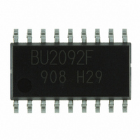
Manufacturer Part Number
BU2092F-E2
Description
IC DRIVER 12BIT S-IN P-OUT SOP18
Manufacturer
Rohm Semiconductor
Type
Driverr
Specifications of BU2092F-E2
Number Of Drivers/receivers
12/0
Voltage - Supply
2.7 V ~ 5.5 V
Mounting Type
Surface Mount
Package / Case
18-SOP
Output Current
25mA
No. Of Outputs
12
Supply Voltage Range
2.7V To 5.5V
Driver Case Style
SOP
No. Of Pins
18
Operating Temperature Range
-20°C To +75°C
Svhc
No SVHC (18-Jun-2010)
Base
RoHS Compliant
Supply Voltage (max)
5.5 V
Supply Voltage (min)
2.7 V
Supply Current
0.025 A
Maximum Operating Temperature
+ 75 C
Mounting Style
SMD/SMT
Minimum Operating Temperature
- 25 C
Output Voltage
2 V to 1 V
Base Number
2092
Rohs Compliant
Yes
Lead Free Status / RoHS Status
Lead free / RoHS Compliant
Protocol
-
Lead Free Status / Rohs Status
Lead free / RoHS Compliant
Other names
BU2092F-E2TR
Available stocks
Company
Part Number
Manufacturer
Quantity
Price

Part Number:
BU2092F-E2
Manufacturer:
ROHM/罗姆
Quantity:
20 000


【BU2092F/BU2092FV】
●Pin descriptions
●Timing chart
© 2009 ROHM Co., Ltd. All rights reserved.
BU2050F,BU2092F,BU2092FV,BU2099FV,BD7851FP,BU2152FS
www.rohm.com
Pin No.
14~18
CLOCK
5~11,
12, 13
CLOCK
DATA
LCK
OE
Qx
17
18
1
2
3
4
×
×
×
×
1.
2.
3.
4.
[Truth Table]
After the power is turned on and the voltage is stabilized, LCK should be activated, after clocking 12 data bits into
the DATA terminal.
Qx parallel output data of the shift register is set after the 12
Since the LCK is a label latch, data is retained in the “L” section and renewed in the “H” section of the LCK.
Data retained in the internal latch circuit is output when the OE is in the “L” section.
Pin Name
Q0~Q11
CLOCK
DATA
DATA
N.C.
LCK
V
V
OE
H
×
×
×
×
×
L
DD
SS
DATA11
Input
“H”
LCK
×
×
×
×
×
DATA10
I/O
O
-
-
-
I
I
I
I
Previous DATA
OE
H
L
×
×
×
×
×
Function
GND
Serial Data Input
Shift clock of DATA (Rising Edge Trigger)
Latch clock of DATA (Rising Edge Trigger)
Parallel Data Output (Nch Open Drain FET)
Non connected
Output Enable (“H” level : output FET is OFF)
Power Supply
DATA9
Latch Data
Output FET
Output (Q0~Q11) Disable
Output (Q0~Q11) Enable
Store “L” in the first stage data of shift register, the previous stage data in the
others. (The conditions of storage register and output have no change.)
Store “H” in the first stage data of shift register, the previous stage data in the
others. (The conditions of storage register and output have no change.)
The data of shift register has no change.
The data of shift register is transferred to the storage register.
The data of storage register has no change.
Fig. 4
Note) Diagram shows a status where a pull-up resistor is connected to output.
9/24
ON
L
th
clock by the LCK.
DATA1
OFF
H
Function
DATA0
DATA11~0
Technical Note
2009.06 - Rev.A
Related parts for BU2092F-E2
Image
Part Number
Description
Manufacturer
Datasheet
Request
R

Part Number:
Description:
Manufacturer:
Rohm Semiconductor
Datasheet:
Part Number:
Description:
Manufacturer:
Rohm Semiconductor
Datasheet:
Part Number:
Description:
Manufacturer:
Rohm Semiconductor
Datasheet:
Part Number:
Description:
Manufacturer:
Rohm Semiconductor
Datasheet:
Part Number:
Description:
Manufacturer:
Rohm Semiconductor
Datasheet:
Part Number:
Description:
Manufacturer:
Rohm Semiconductor
Datasheet:
Part Number:
Description:
Manufacturer:
Rohm Semiconductor
Datasheet:
Part Number:
Description:
Manufacturer:
Rohm Semiconductor
Datasheet:
Part Number:
Description:
Manufacturer:
Rohm Semiconductor
Datasheet:
Part Number:
Description:
Manufacturer:
Rohm Semiconductor
Datasheet:
Part Number:
Description:
Manufacturer:
Rohm Semiconductor
Datasheet:
Part Number:
Description:
Manufacturer:
Rohm Semiconductor
Datasheet:

Part Number:
Description:
DIODE SWITCH 80V 25MA SMD5 TR
Manufacturer:
Rohm Semiconductor
Datasheet: