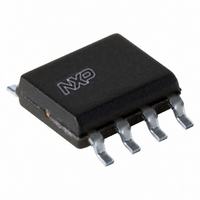
TDA8579T/N1,112 NXP Semiconductors, TDA8579T/N1,112 Datasheet

TDA8579T/N1,112
Specifications of TDA8579T/N1,112
935075970112
TDA8579TD
Related parts for TDA8579T/N1,112
TDA8579T/N1,112 Summary of contents
Page 1
DATA SHEET TDA8579 Dual common-mode rejection differential line receiver Product specification Supersedes data of January 1994 File under Integrated Circuits, IC01 INTEGRATED CIRCUITS 1995 Dec 15 ...
Page 2
Philips Semiconductors Dual common-mode rejection differential line receiver FEATURES Excellent common-mode rejection high frequencies Elimination of source resistance dependency in the common-mode rejection Few external components High supply voltage ripple rejection Low noise Low distortion All pins protected ...
Page 3
Philips Semiconductors Dual common-mode rejection differential line receiver BLOCK DIAGRAM INL 2 TDA8579 IN INR 3 5 GND Fig.1 Block diagram. PINNING SYMBOL PIN DESCRIPTION INL+ 1 positive input left IN 2 common negative input INR+ ...
Page 4
Philips Semiconductors Dual common-mode rejection differential line receiver LIMITING VALUES in accordance with the Absolute Maximum Rating System (IEC 134). SYMBOL PARAMETER V supply voltage CC I repetitive peak output current ORM V AC and DC short-circuit safe voltage sc ...
Page 5
Philips Semiconductors Dual common-mode rejection differential line receiver CHARACTERISTICS kHz; measured in test circuit of Fig.3; unless otherwise specified. CC amb SYMBOL PARAMETER V supply voltage CC I supply ...
Page 6
Philips Semiconductors Dual common-mode rejection differential line receiver V INL INR 1 10 THD (%) Fig.4 Total harmonic distortion as a function of frequency; V 1995 Dec 15 220 ...
Page 7
Philips Semiconductors Dual common-mode rejection differential line receiver 0 CMR (dB 100 Fig.5 Common-mode ...
Page 8
Philips Semiconductors Dual common-mode rejection differential line receiver 40 CMR (dB 100 300 Fig.7 Common-mode rejection ratio as a function of common-mode input voltage kHz (R 0 CMR (dB ...
Page 9
Philips Semiconductors Dual common-mode rejection differential line receiver 30 SVR (dB Fig.9 Supply voltage ripple rejection as a function of frequency; V 1995 Dec Product specification TDA8579 MBD212 ...
Page 10
Philips Semiconductors Dual common-mode rejection differential line receiver PACKAGE OUTLINES DIP8: plastic dual in-line package; 8 leads (300 mil pin 1 index 1 DIMENSIONS (inch dimensions are derived from the original mm dimensions ...
Page 11
Philips Semiconductors Dual common-mode rejection differential line receiver SO8: plastic small outline package; 8 leads; body width 3 pin 1 index 1 e DIMENSIONS (inch dimensions are derived from the original mm dimensions) A UNIT A ...
Page 12
Philips Semiconductors Dual common-mode rejection differential line receiver SOLDERING Introduction There is no soldering method that is ideal for all IC packages. Wave soldering is often preferred when through-hole and surface mounted components are mixed on one printed-circuit board. However, ...
Page 13
Philips Semiconductors Dual common-mode rejection differential line receiver DEFINITIONS Data sheet status Objective specification This data sheet contains target or goal specifications for product development. Preliminary specification This data sheet contains preliminary data; supplementary data may be published later. Product ...


