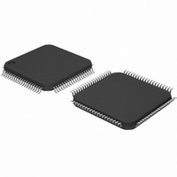
DP83849CVS/NOPB National Semiconductor, DP83849CVS/NOPB Datasheet - Page 28

DP83849CVS/NOPB
Manufacturer Part Number
DP83849CVS/NOPB
Description
IC TXRX ETHERNET PHY DUAL 80TQFP
Manufacturer
National Semiconductor
Type
Transceiverr
Specifications of DP83849CVS/NOPB
Number Of Drivers/receivers
2/2
Protocol
Ethernet
Voltage - Supply
3 V ~ 3.6 V
Mounting Type
Surface Mount
Package / Case
80-TQFP, 80-VQFP
Data Rate
100Mbps
Supply Voltage Range
3V To 3.6V
Logic Case Style
TQFP
No. Of Pins
80
Operating Temperature Range
0°C To +70°C
Msl
MSL 3 - 168 Hours
Filter Terminals
SMD
Rohs Compliant
Yes
Data Rate Max
10Mbps
For Use With
DP83849CVS-EVK - BOARD EVALUATION DP83849CVS
Lead Free Status / RoHS Status
Lead free / RoHS Compliant
Other names
*DP83849CVS
*DP83849CVS/NOPB
DP83849CVS
*DP83849CVS/NOPB
DP83849CVS
Available stocks
Company
Part Number
Manufacturer
Quantity
Price
Company:
Part Number:
DP83849CVS/NOPB
Manufacturer:
NS
Quantity:
618
Company:
Part Number:
DP83849CVS/NOPB
Manufacturer:
Texas Instruments
Quantity:
10 000
www.national.com
4.1.1 Code-group Encoding and Injection
The code-group encoder converts 4-bit (4B) nibble data
generated by the MAC into 5-bit (5B) code-groups for
transmission. This conversion is required to allow control
data to be combined with packet data code-groups. Refer
to Table 13 for 4B to 5B code-group mapping details.
The code-group encoder substitutes the first 8-bits of the
MAC preamble with a J/K code-group pair (11000 10001)
upon transmission. The code-group encoder continues to
replace subsequent 4B preamble and data nibbles with
corresponding 5B code-groups. At the end of the transmit
packet, upon the deassertion of Transmit Enable signal
from the MAC, the code-group encoder injects the T/R
code-group pair (01101 00111) indicating the end of the
frame.
After the T/R code-group pair, the code-group encoder
continuously injects IDLEs into the transmit data stream
until the next transmit packet is detected (reassertion of
Transmit Enable).
4.1.2 Scrambler
The scrambler is required to control the radiated emissions
at the media connector and on the twisted pair cable (for
100BASE-TX applications). By scrambling the data, the
total energy launched onto the cable is randomly distrib-
uted over a wide frequency range. Without the scrambler,
energy levels at the PMD and on the cable could peak
beyond FCC limitations at frequencies related to repeating
5B sequences (i.e., continuous transmission of IDLEs).
The scrambler is configured as a closed loop linear feed-
back shift register (LFSR) with an 11-bit polynomial. The
output of the closed loop LFSR is X-ORd with the serial
NRZ data from the code-group encoder. The result is a
scrambled data stream with sufficient randomization to
decrease radiated emissions at certain frequencies by as
much as 20 dB. The DP83849C uses the PHY_ID (pins
PHYAD [4:1]) to set a unique seed value.
4.1.3 NRZ to NRZI Encoder
After the transmit data stream has been serialized and
scrambled, the data must be NRZI encoded in order to
comply with the TP-PMD standard for 100BASE-TX trans-
mission over Category-5 Unshielded twisted pair cable.
4.1.4 Binary to MLT-3 Convertor
The Binary to MLT-3 conversion is accomplished by con-
verting the serial binary data stream output from the NRZI
encoder into two binary data streams with alternately
phased logic one events. These two binary streams are
then fed to the twisted pair output driver which converts the
voltage to current and alternately drives either side of the
28
transmit transformer primary winding, resulting in a MLT-3
signal.
The 100BASE-TX MLT-3 signal sourced by the PMD Out-
put Pair common driver is slew rate controlled. This should
be considered when selecting AC coupling magnetics to
ensure TP-PMD Standard compliant transition times (3 ns
< Tr < 5 ns).
The 100BASE-TX transmit TP-PMD function within the
DP83849C is capable of sourcing only MLT-3 encoded
data. Binary output from the PMD Output Pair is not possi-
ble in 100 Mb/s mode.
4.2 100BASE-TX RECEIVER
The 100BASE-TX receiver consists of several functional
blocks which convert the scrambled MLT-3 125 Mb/s serial
data stream to synchronous 4-bit nibble data that is pro-
vided to the MII. Because the 100BASE-TX TP-PMD is
integrated, the differential input pins, RD , can be directly
routed from the AC coupling magnetics.
See Figure 7 for a block diagram of the 100BASE-TX
receive function. This provides an overview of each func-
tional block within the 100BASE-TX receive section.
The Receive section consists of the following functional
blocks:
— Analog Front End
— Digital Signal Processor
— Signal Detect
— MLT-3 to Binary Decoder
— NRZI to NRZ Decoder
— Serial to Parallel
— Descrambler
— Code Group Alignment
— 4B/5B Decoder
— Link Integrity Monitor
— Bad SSD Detection
4.2.1 Analog Front End
In addition to the Digital Equalization and Gain Control, the
DP83849C includes Analog Equalization and Gain Control
in the Analog Front End. The Analog Equalization reduces
the amount of Digital Equalization required in the DSP.
4.2.2 Digital Signal Processor
The Digital Signal Processor includes Adaptive Equaliza-
tion with Gain Control and Base Line Wander Compensa-
tion.


