DS33R41+ Maxim Integrated Products, DS33R41+ Datasheet - Page 193
DS33R41+
Manufacturer Part Number
DS33R41+
Description
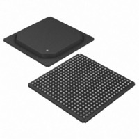
IC TXRX ETHERNET MAP 400-BGA
Manufacturer
Maxim Integrated Products
Type
Transceiverr
Datasheet
1.DS33R41.pdf
(335 pages)
Specifications of DS33R41+
Number Of Drivers/receivers
4/4
Protocol
T1/E1/J1
Voltage - Supply
3.14 V ~ 3.47 V
Mounting Type
Surface Mount
Package / Case
400-BGA
Lead Free Status / RoHS Status
Lead free / RoHS Compliant


12.7 Transceiver Registers
Register Name:
Register Description:
Register Address:
Bit #
Name
Default
Bits 3 and 2: Test Mode Bits (TEST1 and TEST0). Test modes are used to force the output pins of the
transceiver into known states. This can facilitate the checkout of assemblies during the manufacturing process and
also be used to isolate devices from shared buses.
Bit 1: Transceiver Operating Mode (T1/E1). Used to select the operating mode of the framer/formatter (digital)
portion of the transceiver. The operating mode of the LIU must also be programmed.
Bit 0: Software-Issued Reset (SFTRST). A 0-to-1 transition causes the register space in the T1/E1/J1 transceiver
to be cleared. A reset clears all configuration and status registers. The bit automatically clears itself when the reset
has completed.
TEST1
0
0
1
1
0 = T1 operation
1 = E1 operation
TEST0
0
1
0
1
—
7
0
Operate normally
Force all output pins into tri-state (including all I/O pins and parallel port
pins)
Force all output pins low (including all I/O pins except parallel port pins)
Force all output pins high (including all I/O pins except parallel port pins)
TR.MSTRREG
Master Mode Register
00h
—
6
0
—
5
0
Effect On Output Pins
193 of 335
—
4
0
TEST1
3
0
TEST0
2
0
T1/E1
1
0
SFTRST
0
0
Related parts for DS33R41+
Image
Part Number
Description
Manufacturer
Datasheet
Request
R

Part Number:
Description:
MAX7528KCWPMaxim Integrated Products [CMOS Dual 8-Bit Buffered Multiplying DACs]
Manufacturer:
Maxim Integrated Products
Datasheet:
Part Number:
Description:
Single +5V, fully integrated, 1.25Gbps laser diode driver.
Manufacturer:
Maxim Integrated Products
Datasheet:
Part Number:
Description:
Single +5V, fully integrated, 155Mbps laser diode driver.
Manufacturer:
Maxim Integrated Products
Datasheet:
Part Number:
Description:
VRD11/VRD10, K8 Rev F 2/3/4-Phase PWM Controllers with Integrated Dual MOSFET Drivers
Manufacturer:
Maxim Integrated Products
Datasheet:
Part Number:
Description:
Highly Integrated Level 2 SMBus Battery Chargers
Manufacturer:
Maxim Integrated Products
Datasheet:
Part Number:
Description:
Current Monitor and Accumulator with Integrated Sense Resistor; ; Temperature Range: -40°C to +85°C
Manufacturer:
Maxim Integrated Products
Part Number:
Description:
TSSOP 14/A�/RS-485 Transceivers with Integrated 100O/120O Termination Resis
Manufacturer:
Maxim Integrated Products
Part Number:
Description:
TSSOP 14/A�/RS-485 Transceivers with Integrated 100O/120O Termination Resis
Manufacturer:
Maxim Integrated Products
Part Number:
Description:
QFN 16/A�/AC-DC and DC-DC Peak-Current-Mode Converters with Integrated Step
Manufacturer:
Maxim Integrated Products
Part Number:
Description:
TDFN/A/65V, 1A, 600KHZ, SYNCHRONOUS STEP-DOWN REGULATOR WITH INTEGRATED SWI
Manufacturer:
Maxim Integrated Products
Part Number:
Description:
Integrated Temperature Controller f
Manufacturer:
Maxim Integrated Products
Part Number:
Description:
SOT23-6/I�/45MHz to 650MHz, Integrated IF VCOs with Differential Output
Manufacturer:
Maxim Integrated Products
Part Number:
Description:
SOT23-6/I�/45MHz to 650MHz, Integrated IF VCOs with Differential Output
Manufacturer:
Maxim Integrated Products
Part Number:
Description:
EVALUATION KIT/2.4GHZ TO 2.5GHZ 802.11G/B RF TRANSCEIVER WITH INTEGRATED PA
Manufacturer:
Maxim Integrated Products
Part Number:
Description:
QFN/E/DUAL PCIE/SATA HIGH SPEED SWITCH WITH INTEGRATED BIAS RESISTOR
Manufacturer:
Maxim Integrated Products
Datasheet: