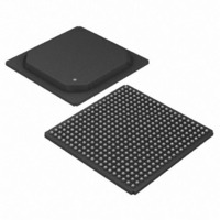
DS33R41+ Maxim Integrated Products, DS33R41+ Datasheet - Page 47

DS33R41+
Manufacturer Part Number
DS33R41+
Description
IC TXRX ETHERNET MAP 400-BGA
Manufacturer
Maxim Integrated Products
Type
Transceiverr
Datasheet
1.DS33R41.pdf
(335 pages)
Specifications of DS33R41+
Number Of Drivers/receivers
4/4
Protocol
T1/E1/J1
Voltage - Supply
3.14 V ~ 3.47 V
Mounting Type
Surface Mount
Package / Case
400-BGA
Lead Free Status / RoHS Status
Lead free / RoHS Compliant
- Current page: 47 of 335
- Download datasheet (2Mb)
The command and status registers for the IMUX function are detailed below:
Table 9-4. Command and Status for the IMUX for Processor Communication
IMUX Configuration Register
IMUX Command Register
IMUX Sync Status Register
IMUX Sync Latched Status Register
IMUX Interrupt Mask Register
Differential Delay Register
Differential Delay Error Interrupt
Enable Register
Differential Delay Latched Status
Register
OOF Interrupt Enable
OOF Latched Status Register
REGISTER
GL.IMXDFDELS
GL.IMXOOFLS
GL.IMXOOFIE
GL.IMXDFEIE
GL.IMXDFD
GL.IMXSLS
GL.IMXSIE
GL.IMXCN
GL.IMXSS
GL.IMXC
47 of 335
NAME
Used to configure the number of links
participating and select T1 or E1.
Used to issue commands for link
management
Provides the real time sync status of
the 4 transmit and receive links
Latched status register for the IMXSS
register.
Interrupt enable bits for Sync Latched
Status bits
Provides the largest differential delay
value for the receive path. Measured
only at link initialization.
Interrupt enable for the differential
delay register.
Latched Status for GL.IMXDFD. Note
that differential delay is measured only
at link initiation.
Interrupt enable for the IMXOOFLS
register.
Indicates out of frame conditions for
both ends of the communication. If
detected, the user must re-initiate all
links.
COMMENTS
Related parts for DS33R41+
Image
Part Number
Description
Manufacturer
Datasheet
Request
R

Part Number:
Description:
MAX7528KCWPMaxim Integrated Products [CMOS Dual 8-Bit Buffered Multiplying DACs]
Manufacturer:
Maxim Integrated Products
Datasheet:

Part Number:
Description:
Single +5V, fully integrated, 1.25Gbps laser diode driver.
Manufacturer:
Maxim Integrated Products
Datasheet:

Part Number:
Description:
Single +5V, fully integrated, 155Mbps laser diode driver.
Manufacturer:
Maxim Integrated Products
Datasheet:

Part Number:
Description:
VRD11/VRD10, K8 Rev F 2/3/4-Phase PWM Controllers with Integrated Dual MOSFET Drivers
Manufacturer:
Maxim Integrated Products
Datasheet:

Part Number:
Description:
Highly Integrated Level 2 SMBus Battery Chargers
Manufacturer:
Maxim Integrated Products
Datasheet:

Part Number:
Description:
Current Monitor and Accumulator with Integrated Sense Resistor; ; Temperature Range: -40°C to +85°C
Manufacturer:
Maxim Integrated Products

Part Number:
Description:
TSSOP 14/A°/RS-485 Transceivers with Integrated 100O/120O Termination Resis
Manufacturer:
Maxim Integrated Products

Part Number:
Description:
TSSOP 14/A°/RS-485 Transceivers with Integrated 100O/120O Termination Resis
Manufacturer:
Maxim Integrated Products

Part Number:
Description:
QFN 16/A°/AC-DC and DC-DC Peak-Current-Mode Converters with Integrated Step
Manufacturer:
Maxim Integrated Products

Part Number:
Description:
TDFN/A/65V, 1A, 600KHZ, SYNCHRONOUS STEP-DOWN REGULATOR WITH INTEGRATED SWI
Manufacturer:
Maxim Integrated Products

Part Number:
Description:
Integrated Temperature Controller f
Manufacturer:
Maxim Integrated Products

Part Number:
Description:
SOT23-6/I°/45MHz to 650MHz, Integrated IF VCOs with Differential Output
Manufacturer:
Maxim Integrated Products

Part Number:
Description:
SOT23-6/I°/45MHz to 650MHz, Integrated IF VCOs with Differential Output
Manufacturer:
Maxim Integrated Products

Part Number:
Description:
EVALUATION KIT/2.4GHZ TO 2.5GHZ 802.11G/B RF TRANSCEIVER WITH INTEGRATED PA
Manufacturer:
Maxim Integrated Products

Part Number:
Description:
QFN/E/DUAL PCIE/SATA HIGH SPEED SWITCH WITH INTEGRATED BIAS RESISTOR
Manufacturer:
Maxim Integrated Products
Datasheet:


