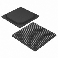
DS33R41+ Maxim Integrated Products, DS33R41+ Datasheet - Page 46

DS33R41+
Manufacturer Part Number
DS33R41+
Description
IC TXRX ETHERNET MAP 400-BGA
Manufacturer
Maxim Integrated Products
Type
Transceiverr
Datasheet
1.DS33R41.pdf
(335 pages)
Specifications of DS33R41+
Number Of Drivers/receivers
4/4
Protocol
T1/E1/J1
Voltage - Supply
3.14 V ~ 3.47 V
Mounting Type
Surface Mount
Package / Case
400-BGA
Lead Free Status / RoHS Status
Lead free / RoHS Compliant
- Current page: 46 of 335
- Download datasheet (2Mb)
9.8.2 IMUX Command Protocol
The format for all commands sent and received in Channel 2 of the IBO Serial Interface is shown in
The MSB for all commands is a “1.” The next 6 bits contain the actual opcode for the command. The LSB is the
even parity calculation for the byte. These commands will be sent and received on Channel 2 of each of the T1/E1
interleaved IBO data. The commands that are possible are outlined in
IMUX link are separate and the Channel 2 for each link will send and receive commands specific to that link. The
microprocessor can disable links that are not to be aggregated.
Figure 9-5. Command Structure for IMUX Function
Table 9-3. Commands Sent and Received on the IMUX Links
COMMAND
Sequence
Link Start
NAME
Rsync
OOF
Nop
M
S
B
"1"
COMMAND BYTE
(P IS EVEN
1000 001P
1000 011P
1000 100P
1111 111P
1sss 010P
PARITY)
Command
TRANSMIT /
RECEIVE
Tx or Rx
Tx or Rx
Tx or Rx
Tx or Rx
Tx or Rx
46 of 335
Initiate the link. The receiver will then search for 3
consecutive sequence numbers.
“sss” contains the frame sequence number for
packet segmentation and reassembly.
This command is sent to indicate to the distant
node that link synchronization has been achieved.
The transmitting device has detected an out of
frame condition.
No operation.
Parity
Even
S
B
L
Table
9-3. Note that the 4 portions of the
COMMENTS
Figure
9-5.
Related parts for DS33R41+
Image
Part Number
Description
Manufacturer
Datasheet
Request
R

Part Number:
Description:
MAX7528KCWPMaxim Integrated Products [CMOS Dual 8-Bit Buffered Multiplying DACs]
Manufacturer:
Maxim Integrated Products
Datasheet:

Part Number:
Description:
Single +5V, fully integrated, 1.25Gbps laser diode driver.
Manufacturer:
Maxim Integrated Products
Datasheet:

Part Number:
Description:
Single +5V, fully integrated, 155Mbps laser diode driver.
Manufacturer:
Maxim Integrated Products
Datasheet:

Part Number:
Description:
VRD11/VRD10, K8 Rev F 2/3/4-Phase PWM Controllers with Integrated Dual MOSFET Drivers
Manufacturer:
Maxim Integrated Products
Datasheet:

Part Number:
Description:
Highly Integrated Level 2 SMBus Battery Chargers
Manufacturer:
Maxim Integrated Products
Datasheet:

Part Number:
Description:
Current Monitor and Accumulator with Integrated Sense Resistor; ; Temperature Range: -40°C to +85°C
Manufacturer:
Maxim Integrated Products

Part Number:
Description:
TSSOP 14/A°/RS-485 Transceivers with Integrated 100O/120O Termination Resis
Manufacturer:
Maxim Integrated Products

Part Number:
Description:
TSSOP 14/A°/RS-485 Transceivers with Integrated 100O/120O Termination Resis
Manufacturer:
Maxim Integrated Products

Part Number:
Description:
QFN 16/A°/AC-DC and DC-DC Peak-Current-Mode Converters with Integrated Step
Manufacturer:
Maxim Integrated Products

Part Number:
Description:
TDFN/A/65V, 1A, 600KHZ, SYNCHRONOUS STEP-DOWN REGULATOR WITH INTEGRATED SWI
Manufacturer:
Maxim Integrated Products

Part Number:
Description:
Integrated Temperature Controller f
Manufacturer:
Maxim Integrated Products

Part Number:
Description:
SOT23-6/I°/45MHz to 650MHz, Integrated IF VCOs with Differential Output
Manufacturer:
Maxim Integrated Products

Part Number:
Description:
SOT23-6/I°/45MHz to 650MHz, Integrated IF VCOs with Differential Output
Manufacturer:
Maxim Integrated Products

Part Number:
Description:
EVALUATION KIT/2.4GHZ TO 2.5GHZ 802.11G/B RF TRANSCEIVER WITH INTEGRATED PA
Manufacturer:
Maxim Integrated Products

Part Number:
Description:
QFN/E/DUAL PCIE/SATA HIGH SPEED SWITCH WITH INTEGRATED BIAS RESISTOR
Manufacturer:
Maxim Integrated Products
Datasheet:


