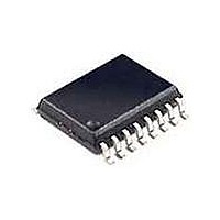
TD340ID STMicroelectronics, TD340ID Datasheet - Page 18

TD340ID
Manufacturer Part Number
TD340ID
Description
MOSFET & Power Driver ICs H-Bridge Quad MOSFET
Manufacturer
STMicroelectronics
Type
High Side/Low Sider
Datasheet
1.TD340ID.pdf
(21 pages)
Specifications of TD340ID
Supply Voltage (min)
6.5 V
Supply Current
7 mA
Maximum Power Dissipation
500 mW
Maximum Operating Temperature
+ 125 C
Mounting Style
SMD/SMT
Package / Case
SO-20
Bridge Type
H Bridge
Minimum Operating Temperature
- 40 C
Number Of Drivers
4
Number Of Outputs
4
Output Current
1.5 A
Lead Free Status / Rohs Status
Lead free / RoHS Compliant
Available stocks
Company
Part Number
Manufacturer
Quantity
Price
TD340
APPLICATION CIRCUIT DIAGRAMS
The following schematics show typical application circuits. The first one is a simple, standalone system,
while the other one is C driven and includes advanced features like standby mode and reversed battery
active protection.
Simple standalone system
Figure 9 shows a basic use of the TD340. The speed is controlled with a simple adjustable resistor.
Direction is controlled with a switch.
Internal PWM generator is used, frequency is set by the capacitor C3.
Note that the C2 capacitor (220nF) is included because it is needed by the internal TD340 circuit.
Interface lines for microcontroller are not used:
Standby is tied to 5V (Vout),
WD and CWD are tied to ground,
Reset and Temperature outputs are left unconnected.
Reversed battery protection is provided by the means of the diode D2.
Transistors Q1H, Q1L, Q2H, Q2L are to be chosen depending on the motor characteristics.
For example, STP30NE03L are 30V, 30A devices with gate capacitance of about 1nF. For these MOS,
22nF bootstrap capacitors are adequate.
Resistors R1 to R4 are used to control the rise and fall times on the MOS gates, and are also useful to
avoid oscillation of the gate voltage due to the parasitic inductance of lines in conjunction with the gate
capacitance. Typical values for resistors R1 to R4 are from 10 to 100 ohms.
Capacitor C6 is used to store energy and to filter the voltage across the bridge.
Applications:
Small domestic motorized equipments, battery-powered electrical tools, ...
Complete, C driven system
The next schematic (figure 10) shows a complete system driven by a C.
The auto-reload timer feature of ST6 C family is used to easily generate the PWM command signal
(TD340 internal generator is not used, CF pin is connected to ground).
Transil diode D3 can be added as a security to avoid overvoltage transients if the MOS are all driven off
when the motor is running. For example, it can happen if TD340 is put in standby or disable state while
motor is running.
Applications:
- Automotive: advanced window lift systems, wiper systems, ...
- Industrial: battery-powered motor systems, electric door opening, ...
18/21


