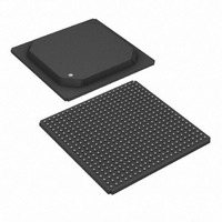
DS32508N+ Maxim Integrated Products, DS32508N+ Datasheet - Page 33

DS32508N+
Manufacturer Part Number
DS32508N+
Description
IC LIU DS3/E3/STS-1 484-BGA
Manufacturer
Maxim Integrated Products
Type
Line Interface Units (LIUs)r
Datasheet
1.DS32506N.pdf
(130 pages)
Specifications of DS32508N+
Protocol
IEEE 1149.1
Voltage - Supply
1.8V, 3.3V
Mounting Type
Surface Mount
Package / Case
484-BGA
Lead Free Status / RoHS Status
Lead free / RoHS Compliant
Number Of Drivers/receivers
-
In E3 mode, HDB3 decoding is performed, and
causes one of the following code violations:
In any cycle where
asserted to flag an EXZ, the
toggled on every BPV, whether part of a valid B3ZS/HDB3 codeword or not.
8.3.6.3
The polarity of
Normally, data is output on the
these pins on the rising edge of RCLK, pull the
8.3.6.4
The RCLK,
protection switching and redundant-LIU applications. This capability supports system configurations where two or
more LIUs are wire-ORed together and a system processor selects one to be active. To disable these pins, set the
PORT.CR2:ROD configuration bit.
8.3.7 Power-Down
To minimize power consumption when the receiver is not being used, assert the
PORT.CR1:RPD configuration bit (per port). When the receiver is powered down, the RCLK, RPOS/RDAT, and
RNEG/RLCV
8.3.8 Input Failure Detection
The LIU receiver can detect opens and shorts on the
detects the following problems, collectively labeled type 1 failures: open
common-mode
LIU.SR:RFAIL1. RFAIL1 is cleared when activity is detected on both
If LIU.CR2:RFL2E = 1, the receiver also detects a type 2 failure, which is an open or high-impedance path between
RXP
normally presents a low-impedance path between
an 40 μ A DC current source to
greater than about 5k Ω the receiver declares a type 2 failure on LIU.SR:RFAIL2. When the type 2 failure detection
circuitry is enabled, internal termination must be disabled (LIU.CR2:RTRE = 0) and external termination must not
be present or a type 2 failure will not be detected because the impedance of the termination is below the type 2
failure threshold.
and RXN. In a board with the external components shown in
When
–
–
–
When
–
–
When
–
–
–
When
–
RCLK Inversion
Receiver Output Disable
A BPV immediately preceded by a valid pulse (B, V).
A BPV with the same polarity as the last BPV.
The third zero in an EXZ.
A BPV immediately preceded by a valid pulse (B, V).
A BPV with the same polarity as the last BPV.
A BPV immediately preceded by a valid pulse (B, V) or by a valid pulse and a zero (B, 0, V).
A BPV with the same polarity as the last BPV.
The fourth zero in an EXZ.
A BPV with the same polarity as the last BPV.
RPOS/RDAT
pins are disabled (high impedance). In addition, the
L
8
L
8
L
1 8
L
1 8
RXP/RXN
INE.RCR:E3CVE = 0:
INE.RCR:E3CVE = 1:
INE.RCR:E3CVE = 0:
INE.RCR:E3CVE = 1:
RCLK
RLCV
can be inverted to support a glueless interface to a variety of neighboring components.
short to V
and
is asserted to flag a BPV, the
RXP
RDAT
RPOS/RDAT
RNEG/RLCV
and measures the impedance between
DD
pin outputs a zero. The state bit that tracks the polarity of the last BPV is
, and common-mode
and
pins can be disabled (put in a high-impedance state) to support
RCLKI
RLCV
RNEG/RLCV
RXP
33 of 130
pin high or set the PORT.INV:RCLKI configuration bit.
is asserted during any
RXP
and RXN. To detect a type 2 failure, the receiver connects
RDAT
RXP/RXN
and
pins on the falling edge of RCLK. To output data on
RXP
pin outputs a one. In any cycle where
RXN
Figure 4-1
RXP
short to V
and
differential inputs. By default, the receiver
and RXN.
RXP
RXN
RXP
RCLK
or
connection, open
Figure
SS
pins become high impedance.
and RXN. When this impedance is
. Type 1 failures are reported on
cycle where the data on
DS32506/DS32508/DS32512
4-2, the receive transformer
RPD
pin (all ports) or the
RXN
connection,
RLCV
RDAT
is


