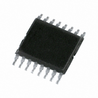
PTN3342DH,112 NXP Semiconductors, PTN3342DH,112 Datasheet - Page 14

PTN3342DH,112
Manufacturer Part Number
PTN3342DH,112
Description
IC HS DIFF LINE RECEIVER 16TSSOP
Manufacturer
NXP Semiconductors
Type
Transceiverr
Datasheet
1.PTN3342D112.pdf
(16 pages)
Specifications of PTN3342DH,112
Number Of Drivers/receivers
0/4
Protocol
RS644
Voltage - Supply
3 V ~ 3.6 V
Mounting Type
Surface Mount
Package / Case
16-TSSOP
Lead Free Status / RoHS Status
Lead free / RoHS Compliant
Other names
935271107112
PTN3342DH
PTN3342DH
PTN3342DH
PTN3342DH
Philips Semiconductors
15. Abbreviations
16. Revision history
Table 13.
PTN3342_2
Product data sheet
Document ID
PTN3342_2
Modifications:
PTN3342-01
(9397 750 08484)
Revision history
Release date
20060810
20040105
•
•
•
•
•
•
[3]
[4]
[5]
[6]
[7]
[8]
[9]
Table 12.
Acronym
ANSI
EMI
LVDS
LVTTL
TTL
The format of this data sheet has been redesigned to comply with the new presentation and
information standard of Philips Semiconductors.
Section 2
Figure 1 “Functional diagram of
pin 11 = 3Y)
Table 4 “Limiting
“electrostatic discharge voltage”
Table 6 “Static characteristics”
– updated values for I
– changed symbol “Z
added
These transparent plastic packages are extremely sensitive to reflow soldering conditions and must on no
account be processed through more than one soldering cycle or subjected to infrared reflow soldering with
peak temperature exceeding 217 C
body peak temperature must be kept as low as possible.
These packages are not suitable for wave soldering. On versions with the heatsink on the bottom side, the
solder cannot penetrate between the printed-circuit board and the heatsink. On versions with the heatsink
on the top side, the solder might be deposited on the heatsink surface.
If wave soldering is considered, then the package must be placed at a 45 angle to the solder wave
direction. The package footprint must incorporate solder thieves downstream and at the side corners.
Wave soldering is suitable for LQFP, QFP and TQFP packages with a pitch (e) larger than 0.8 mm; it is
definitely not suitable for packages with a pitch (e) equal to or smaller than 0.65 mm.
Wave soldering is suitable for SSOP, TSSOP, VSO and VSSOP packages with a pitch (e) equal to or larger
than 0.65 mm; it is definitely not suitable for packages with a pitch (e) equal to or smaller than 0.5 mm.
Image sensor packages in principle should not be soldered. They are mounted in sockets or delivered
pre-mounted on flex foil. However, the image sensor package can be mounted by the client on a flex foil by
using a hot bar soldering process. The appropriate soldering profile can be provided on request.
Hot bar soldering or manual soldering is suitable for PMFP packages.
10 A typ; 20 A max”
Section 15 “Abbreviations”
“Features”, second bullet item: changed “400 Mbps” to “400 Mbit/s”
Abbreviations
Data sheet status
Product data sheet
Product data
values”: added symbol “V
Description
American National Standards Institute
ElectroMagnetic Interference
Low Voltage Differential Signaling
Low Voltage Transistor-Transistor Logic
Transistor-Transistor Logic
(t)
I
Rev. 02 — 10 August 2006
(condition V
” to “R
:
T
” and added parameter description “termination resistance”
PTN3342”: corrected nY pin names (pin 3 = 1Y; pin 5 = 2Y;
I
= 2.4 V) from “ 1.2 A min; 3 A typ” to “0 A min;
10 C measured in the atmosphere of the reflow oven. The package
esd
” and changed parameter from “ESD” to
Change notice
-
853-2444 A14997
(20031215)
High speed differential line receiver
© Koninklijke Philips Electronics N.V. 2006. All rights reserved.
Supersedes
PTN3342-01
-
PTN3342
14 of 16


