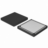
AMIS49587C5872RG ON Semiconductor, AMIS49587C5872RG Datasheet - Page 53

AMIS49587C5872RG
Manufacturer Part Number
AMIS49587C5872RG
Description
IC MODEM PLC 50/60MHZ 52QFN
Manufacturer
ON Semiconductor
Datasheet
1.AMIS49587C5871RG.pdf
(55 pages)
Specifications of AMIS49587C5872RG
Baud Rates
Selectable
Interface
SCI
Voltage - Supply
3 V ~ 3.6 V
Mounting Type
Surface Mount
Package / Case
52-TQFN Exposed Pad
Lead Free Status / RoHS Status
Lead free / RoHS Compliant
Data Format
-
Available stocks
Company
Part Number
Manufacturer
Quantity
Price
Company:
Part Number:
AMIS49587C5872RG
Manufacturer:
Seagate
Quantity:
1 000
7.5.1.2 Data Counters
is used to know whether the counters must be reset or not (00: no reset, 01: reset) after reading them out.
There are 6 counters coded on 4 bytes each, which indicates:
Request Format:
Confirm Format:
7.5.1.3 DataStats
byte which is used to know whether the counters must be reset or not (00: no reset, 01: reset) after reading them out.
If the AMIS- -49587 is synchronized the counters consist of 30 bytes:
If the AMIS- -49587 is not synchronized the counters consist of 36 bytes:
Request Format:
Confirm Format:
If the AMIS- -49587 is synchronized:
If the AMIS- -49587 is not synchronized:
7.5.2 AccessDB_Confirm
See paragraph AccessDB_Confirm.
7.5.3 AccessDB_Error
See paragraph AccessDB_Error.
<STX>
<STX>
<STX>
<STX>
<STX>
The Data Counters request is used to read the value of the data counters in the AMIS- -49587. It contains one byte which
The DataStats request is used to read the value of the current data statistics in the AMIS- -49587. The request contains one
1. number of CRC OK frames received
2. number of CRC not OK frames received
3. number of repeated frames
4. number of transmitted frames
5. number of corrected frames (with option Pad Correcting)
6. number of frames with bad Frame Indicator received
1. The value of signal and noise (S0, N0, S1, N1) for the last subframe received (4 * 2 bytes) + the method and gain
2. The method, gain and SNR (S0/N0, S1/N1) on the 5 last time slots in reception mode (5 * 4 bytes) + 1 byte to know
1. The values of the real and imaginary parts of the signal for each frequency (I0, Q0, I1, Q1),
2. for the 4 last calculated time- -slots (4 * (4 * 2 bytes) )
3. The current position in the board (1 byte)
4. The software reception gain (1 byte)
5. The hardware reception gain (1 byte)
6. The R_ALC value (1 byte)
used to demodulate this subframe (2 * 1 byte)
the actual position in the table
0x1D(Length)
0x06(Length)
0x06(Length)
0x23(Length)
0x29(Length)
0x41 (AccessDB_Request)
0x41 (AccessDB_Request)
0x42 (AccessDB_Confirm)
0x42 (AccessDB_Confirm)
0x42 (AccessDB_Confirm)
http://onsemi.com
53
0x0D00
0x0D00
0x1000
0x1000
0x1000
Rep_Frames (4 bytes), Tr_Frames (4 bytes),
(1 byte), GainHard (1 byte), R_ALC (1 byte)
I0,I1,Q1 (32 bytes), Pos (1 byte), GainSoft
Corr_Frames (4 bytes), FI_NOK (4 bytes)
CRC_OK (4 bytes), CRC_NOK (4 bytes),
Signal_noise_subframe (10 bytes),
Request Counters (1 byte)
SNRreception (20 bytes)
Reset Counters (1 byte)
CHK
CHK
CHK
CHK
CHK


