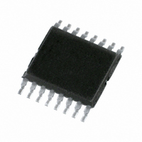
PCA9541APW/03,112 NXP Semiconductors, PCA9541APW/03,112 Datasheet - Page 7

PCA9541APW/03,112
Manufacturer Part Number
PCA9541APW/03,112
Description
IC I2C 2:1 SELECTOR 16-TSSOP
Manufacturer
NXP Semiconductors
Datasheet
1.PCA9541ABS03118.pdf
(41 pages)
Specifications of PCA9541APW/03,112
Package / Case
16-TSSOP
Applications
2-Channel I²C Multiplexer
Interface
I²C, SMBus
Voltage - Supply
2.3 V ~ 5.5 V
Mounting Type
Surface Mount
Maximum Operating Frequency
400 KHz
Maximum Operating Temperature
+ 85 C
Minimum Operating Temperature
- 40 C
Mounting Style
SMD/SMT
Supply Voltage (max)
5.5 V
Supply Voltage (min)
2.3 V
Lead Free Status / RoHS Status
Lead free / RoHS Compliant
Lead Free Status / RoHS Status
Lead free / RoHS Compliant, Lead free / RoHS Compliant
Other names
568-4937-5
935289366112
935289366112
NXP Semiconductors
8. Functional description
PCA9541A_3
Product data sheet
8.1 Device address
8.2 Command Code
Refer to
Following a START condition, the upstream master that wants to control the I
make a status check must send the address of the slave it is accessing. The slave
address of the PCA9541A is shown in
resistors are incorporated on the hardware selectable pins and they must be pulled HIGH
or LOW.
The last bit of the slave address defines the operation to be performed. When set to
logic 1 a read is selected, while logic 0 selects a write operation.
Remark: Reserved I
with:
Following the successful acknowledgement of the slave address, the bus master will send
a byte to the PCA9541A, which will be stored in the Command Code register.
The 2 LSBs are used as a pointer to determine which register will be accessed.
If the auto-increment flag is set (AI = 1), the two least significant bits of the Command
Code are automatically incremented after a byte has been read or written. This allows the
user to program the registers sequentially or to read them sequentially.
Fig 5.
Fig 6.
•
•
•
‘reserved for future use’ I
slave devices that use the 10-bit addressing scheme (1111 0XX)
During a read operation, the contents of these bits will roll over to 00b after the last
allowed register is accessed (10b).
Figure 1 “Block diagram of
Slave address
Command Code
2
C-bus addresses must be used with caution since they can interfere
Rev. 03 — 16 July 2009
2-to-1 I
2
C-bus addresses (1111 1XX)
0
1
2
fixed
0
C-bus master selector with interrupt logic and reset
1
PCA9541A”.
auto-increment
0
1
Figure
AI
A3
selectable
hardware
0
A2
5. To conserve power, no internal pull-up
0
A1
register number
B1
002aab391
A0 R/W
002aab390
B0
PCA9541A
© NXP B.V. 2009. All rights reserved.
2
C-bus or
7 of 41


