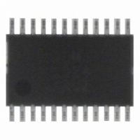
ADM1024ARUZ ON Semiconductor, ADM1024ARUZ Datasheet - Page 15

ADM1024ARUZ
Manufacturer Part Number
ADM1024ARUZ
Description
IC MONITOR SYS TEMP/VOLT 24TSSOP
Manufacturer
ON Semiconductor
Datasheet
1.ADM1024ARUZ.pdf
(29 pages)
Specifications of ADM1024ARUZ
Applications
PC's, PDA's
Interface
Serial
Voltage - Supply
2.8 V ~ 5.5 V
Package / Case
24-TSSOP
Mounting Type
Surface Mount
Temperature Sensor Function
Temp Sensor
Output Type
Digital
Package Type
TSSOP
Operating Temperature (min)
0C
Operating Temperature (max)
100C
Operating Temperature Classification
Commercial
Operating Supply Voltage (typ)
3.3V
Operating Supply Voltage (max)
5.5V
Full Temp Accuracy
+/- 2 C , +/- 3 C
Digital Output - Bus Interface
SMBus
Digital Output - Number Of Bits
10 bit
Supply Voltage (max)
12 V
Supply Voltage (min)
2.5 V
Maximum Operating Temperature
+ 100 C
Minimum Operating Temperature
0 C
Supply Current
1.4 mA
Lead Free Status / RoHS Status
Lead free / RoHS Compliant
Available stocks
Company
Part Number
Manufacturer
Quantity
Price
Part Number:
ADM1024ARUZ
Manufacturer:
ADI/亚德诺
Quantity:
20 000
Analog Output
unsigned 8−bit DAC that produces 0 V to 2.5 V. The analog
output register defaults to FF during power−on reset, which
produces maximum fan speed. The analog output may be
amplified and buffered with external circuitry such as an op
amp and transistor to provide fan speed control.
When using any of these circuits, the following points should be
noted:
The ADM1024 has a single analog output from an
Suitable fan drive circuits are given in Figure 19 to Figure 24.
Figure 20. Fan Drive Circuit with Op Amp and PNP
1. All of these circuits will provide an output range
2. To amplify the 2.5 V range of the analog output up
3. Care must be taken when choosing the op amp to
4. The op amp may be powered from the 12 V rail
5. If the op amp is powered from −12 V, precautions
Figure 19. Fan Drive Circuit with Op Amp and
AOUT
from 0 V to almost 12 V, apart from Figure 25
which loses the base−emitter voltage drop of Q1
due to the emitter−follower configuration.
to 12 V, the gain of these circuits needs to be
around 4.8.
ensure that its input common−mode range and
output voltage swing are suitable.
alone or from 12 V. If it is powered from 12 V,
then the input common− mode range should
include ground to accommodate the minimum
output voltage of the DAC, and the output voltage
should swing below 0.6 V to ensure that the
transistor can be turned fully off.
such as a clamp diode to ground may be needed to
prevent the base−emitter junction of the output
transistor being reverse−biased in the unlikely
event that the output of the op amp should swing
negative for any reason.
AOUT
R1
10kΩ
R1
10kΩ
Emitter−Follower
1/4
LM324
1/4
LM324
Transistor
R3
1kΩ
R2
39kΩ
R2
36kΩ
R4
1kΩ
12V
Q1
BD136
2SA968
12V
Q1
2N2219A
http://onsemi.com
15
Figure 22. Discrete Fan Drive Circuit with P−Channel
Figure 23. Discrete Fan Drive Circuit with P−Channel
Figure 24. Discrete Fan Drive Circuit with Bipolar
AOUT
Figure 21. Fan Driver Circuit with Op Amp and
AOUT
AOUT
AOUT
R1
100kΩ
MBT3904
MOSFET, Single Supply
Q1/Q2
DUAL
R1
100kΩ
R1
4.7kΩ
MOSFET, Dual Supply
R1
10kΩ
P−Channel MOSFET
Output, Dual Supply
MBT3904
MTB3904
Q1/Q2
DUAL
Q1/Q2
DUAL
–12V
1/4
LM324
R2
100kΩ
R5
100kΩ
R2
100kΩ
R2
100kΩ
R2
39kΩ
R4
10kΩ
R3
100kΩ
R3
39kΩ
Q3
BC556
2N3906
R3
3.9kΩ
R4
1kΩ
R3
3.9kΩ
R4
1kΩ
12V
12V
12V
Q3
IRF9620
Q1
IRF9620
Q3
IRF9620
12V
Q4
BD132
TIP32A


