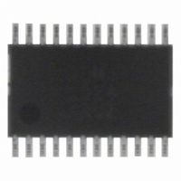
ADM1024ARUZ ON Semiconductor, ADM1024ARUZ Datasheet - Page 20

ADM1024ARUZ
Manufacturer Part Number
ADM1024ARUZ
Description
IC MONITOR SYS TEMP/VOLT 24TSSOP
Manufacturer
ON Semiconductor
Datasheet
1.ADM1024ARUZ.pdf
(29 pages)
Specifications of ADM1024ARUZ
Applications
PC's, PDA's
Interface
Serial
Voltage - Supply
2.8 V ~ 5.5 V
Package / Case
24-TSSOP
Mounting Type
Surface Mount
Temperature Sensor Function
Temp Sensor
Output Type
Digital
Package Type
TSSOP
Operating Temperature (min)
0C
Operating Temperature (max)
100C
Operating Temperature Classification
Commercial
Operating Supply Voltage (typ)
3.3V
Operating Supply Voltage (max)
5.5V
Full Temp Accuracy
+/- 2 C , +/- 3 C
Digital Output - Bus Interface
SMBus
Digital Output - Number Of Bits
10 bit
Supply Voltage (max)
12 V
Supply Voltage (min)
2.5 V
Maximum Operating Temperature
+ 100 C
Minimum Operating Temperature
0 C
Supply Current
1.4 mA
Lead Free Status / RoHS Status
Lead free / RoHS Compliant
Available stocks
Company
Part Number
Manufacturer
Quantity
Price
Part Number:
ADM1024ARUZ
Manufacturer:
ADI/亚德诺
Quantity:
20 000
Temperature Interrupt Modes
interrupts for out−of−limit temperature measurements from
the internal or external sensors. Temperature errors can
generate an interrupt on the INT pin along with other
interrupts, but there is also a separate THERM pin that
generates an interrupt only for temperature errors.
illustrated in Figure 33 Assuming that the temperature starts
off within the programmed limits and that temperature
interrupt sources are not masked, INT will go low if the
temperature measured by any of the internal or external
sensors exceeds the programmed high temperature limit for
that sensor, or the hardware limits in register 13h, 14h, 17h,
or 18h.
REGISTERS
AND LIMIT
The ADM1024 has two distinct methods of producing
Operation of the INT output for temperature interrupts is
VALUE
FROM
VID0/IRQ0
VID1/IRQ1
VID2/IRQ2
VID3/IRQ3
VID4/IRQ4
CONFIGURATION
VALUE
HIGH
LIMIT
LOW
LIMIT
REGISTER 2
REGISTER
CHANNEL
MODE
4
5
6
7
6
7
1 = OUT
LIMIT
OF
FROM BUS
MASKING
DATA
EXT. TEMP1
RESERVED
RESERVED
Figure 32. Interrupt Register Structure
FAN1/AIN1
FAN2/AIN2
INT. TEMP
D1 FAULT
D2 FAULT
2.5V/EXT.
REGISTERS
VID0–VID4
THERM
TEMP 2
+5.0V
+12V
V
V
(SAME BIT ORDER AS
STATUS REGISTERS)
REGISTERS 1 AND 2
CCP2
CCP1
V
INTERRUPT MASK
16 MASK BITS
CC
IN
CI
IN
http://onsemi.com
0
1
2
3
4
5
6
7
0
1
2
3
4
5
6
7
REGISTER 1
INTERRUPT
REGISTER 2
INTERRUPT
STATUS
STATUS
20
STATUS
1005C
ACPI
CONTROL METHODS
CLEAR EVENT
905C
805C
705C
605C
505C
405C
MASK
MASK GATING y 11
INT
Figure 33. Operation of INT for Temperature
BIT
BIT
TEMP
1
1
1
ACPI AND DEFAULT CONTROL METHODS
ADJUST TEMPERATURE LIMIT VALUES.
THERM
Interrupts
1
1
INT_ENABLE
CONFIGURATION
THERM
CLEAR
REGISTER 1
1
1
HIGH LIMIT
LOW LIMIT
INT_CLEAR
INT
THERM


