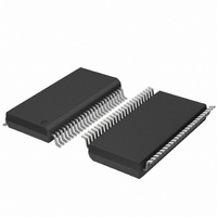
PDI1284P11DGG,518 NXP Semiconductors, PDI1284P11DGG,518 Datasheet - Page 11

PDI1284P11DGG,518
Manufacturer Part Number
PDI1284P11DGG,518
Description
IC TXRX/BUFFER PARALLEL 48-TSSOP
Manufacturer
NXP Semiconductors
Datasheet
1.PDI1284P11DGG518.pdf
(16 pages)
Specifications of PDI1284P11DGG,518
Applications
PCI-to-PCI Bridge
Interface
PCI
Voltage - Supply
3 V ~ 3.6 V
Package / Case
48-TSSOP
Mounting Type
Surface Mount
Lead Free Status / RoHS Status
Lead free / RoHS Compliant
Other names
935223080518
PDI1284P11DGG-T
PDI1284P11DGG-T
PDI1284P11DGG-T
PDI1284P11DGG-T
NXP Semiconductors
Table 10.
PDI1284P11_3
Product data sheet
Output
An
Bn, Yn
Fig 8.
Fig 9.
a. Input pulse definition
b. Test circuit
C
R
R
Test conditions for propagation delays are given in
Test circuit for An, Bn and Yn outputs; slew rate B/Y side
I
Output impedance
O
L
L
T
Test conditions for An, Bn and Yn outputs
is measured by forcing 0.5V
= load capacitance includes jig and probe capacitance.
= load resistance.
= termination resistance should be equal to the output impedance of the pulse generator.
V
3.0 V
3.0 V
I
V
1.5 V
1.5 V
M
negative
positive
1 MHz
Repetition
rate
1 MHz
pulse
pulse
CC
G
0 V
0 V
V
V
on the output. The output impedance can then be calculated as R
I
I
V I
90 %
10 %
Rev. 03 — 25 August 2008
R T
t
t
r
f
t
500 ns
500 ns
W
V
V
M
M
DUT
DUT
V
V
10 %
90 %
Table
CC
CC
10, test conditions for slew rate are given in
I
O
V O
001aai299
t
t
W
W
V
t
3 ns
3 ns
r
CC
/ 2
C L
R L
10 %
90 %
V
V
3.3 V parallel interface transceiver/buffer
M
M
t
3 ns
3 ns
f
t
t
r
f
001aai296
001aai298
90 %
10 %
V
GND
EXT
Switch position
t
GND
GND
PLH
, t
PDI1284P11
PZH
o
Table 8
= 0.5V
© NXP B.V. 2008. All rights reserved.
CC
t
GND
V
PHL
EXT
/ I
, t
O
= 2.8 V
PHZ
.
11 of 16


