ADG409BNZ Analog Devices Inc, ADG409BNZ Datasheet - Page 13
ADG409BNZ
Manufacturer Part Number
ADG409BNZ
Description
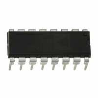
IC MULTIPLEXER DUAL 4X1 16DIP
Manufacturer
Analog Devices Inc
Series
LC²MOSr
Type
Analog Multiplexerr
Datasheet
1.ADG408BNZ.pdf
(16 pages)
Specifications of ADG409BNZ
Function
Multiplexer
Circuit
2 x 4:1
On-state Resistance
100 Ohm
Voltage Supply Source
Single Supply
Voltage - Supply, Single/dual (±)
5V, 12V
Current - Supply
100µA
Operating Temperature
-40°C ~ 85°C
Mounting Type
Through Hole
Package / Case
16-DIP (0.300", 7.62mm)
No. Of Circuits
2
Supply Current
100µA
On State Resistance Max
40ohm
Supply Voltage Range
12V, ± 15V
Operating Temperature Range
-40°C To +85°C
Analog Switch Case Style
DIP
Package
16PDIP
Maximum On Resistance
100@±15V Ohm
Maximum Propagation Delay Bus To Bus
130(Typ)@12V@-40C to 85C|250@±15V@-40C to 85C ns
Maximum High Level Output Current
20 mA
Multiplexer Architecture
4:1
Maximum Turn-off Time
60(Typ)@12V ns
Maximum Turn-on Time
150@±15V ns
Power Supply Type
Single|Dual
Multiplexer Configuration
Dual 4:1
Number Of Inputs
8
Number Of Outputs
2
Number Of Channels
2
Analog Switch On Resistance
100@±15VOhm
Analog Switch Turn On Time
150ns
Analog Switch Turn Off Time
60ns
Package Type
PDIP
Power Supply Requirement
Single/Dual
Single Supply Voltage (min)
5V
Single Supply Voltage (typ)
12V
Single Supply Voltage (max)
12V
Dual Supply Voltage (typ)
±15V
Dual Supply Voltage (max)
±22V
Power Dissipation
470mW
Mounting
Through Hole
Pin Count
16
Operating Temp Range
-40C to 85C
Operating Temperature Classification
Industrial
Lead Free Status / RoHS Status
Lead free / RoHS Compliant
Lead Free Status / RoHS Status
Lead free / RoHS Compliant, Lead free / RoHS Compliant
Available stocks
Company
Part Number
Manufacturer
Quantity
Price
Company:

Part Number:
ADG409BNZ
Manufacturer:
NXP
Quantity:
677
Part Number:
ADG409BNZ
Manufacturer:
ADI/亚德诺
Quantity:
20 000


TERMINOLOGY
R
Ohmic resistance between D and S.
ΔR
Difference between the R
I
Source leakage current when the switch is off.
I
Drain leakage current when the switch is off.
I
Channel leakage current when the switch is on.
V
Analog voltage on Terminal D and Terminal S.
C
Channel input capacitance for off condition.
C
Channel output capacitance for off condition.
C
On switch capacitance.
C
Digital input capacitance.
t
Delay time between the 50% and 90% points of the digital input
and switch on condition.
t
Delay time between the 50% and 90% points of the digital input
and switch off condition.
ON
OFF
S
D
D
ON
S
D
D
IN
D
, I
(OFF)
(OFF)
, C
(OFF)
ON
(V
(OFF)
(EN)
S
(EN)
(ON)
S
S
)
(ON)
ON
of any two channels.
Rev. C | Page 13 of 16
t
Delay time between the 50% and 90% points of the digital
inputs and the switch on condition when switching from one
address state to another.
t
Off time measured between the 80% point of both switches
when switching from one address state to another.
V
Maximum input voltage for Logic 0.
V
Minimum input voltage for Logic 1.
I
Input current of the digital input.
Crosstalk
A measure of unwanted signal that is coupled through from one
channel to another as a result of parasitic capacitance.
Off Isolation
A measure of unwanted signal coupling through an off channel.
Charge Injection
A measure of the glitch impulse transferred from the digital
input to the analog output during switching.
I
Positive supply current.
I
Negative supply current.
TRANSITION
OPEN
INL
DD
SS
INL
INH
(I
INH
)
ADG408/ADG409
Related parts for ADG409BNZ
Image
Part Number
Description
Manufacturer
Datasheet
Request
R

Part Number:
Description:
±1.7g Dual-Axis IMEMS Accelerometer Evaluation Board
Manufacturer:
Analog Devices Inc
Datasheet:

Part Number:
Description:
Inertial Sensor Evaluation System
Manufacturer:
Analog Devices Inc
Datasheet:
Part Number:
Description:
Manufacturer:
Analog Devices Inc
Datasheet:
Part Number:
Description:
Manufacturer:
Analog Devices Inc
Datasheet:
Part Number:
Description:
Manufacturer:
Analog Devices Inc
Datasheet:
Part Number:
Description:
Manufacturer:
Analog Devices Inc
Datasheet:
Part Number:
Description:
Manufacturer:
Analog Devices Inc
Datasheet:
Part Number:
Description:
Manufacturer:
Analog Devices Inc
Datasheet:
Part Number:
Description:
Manufacturer:
Analog Devices Inc
Datasheet:
Part Number:
Description:
Manufacturer:
Analog Devices Inc
Datasheet:
Part Number:
Description:
Manufacturer:
Analog Devices Inc
Datasheet:
Part Number:
Description:
Manufacturer:
Analog Devices Inc
Datasheet:
Part Number:
Description:
Manufacturer:
Analog Devices Inc
Datasheet: