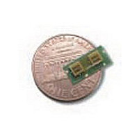
HPMD7904TR1 Avago Technologies US Inc., HPMD7904TR1 Datasheet - Page 12

HPMD7904TR1
Manufacturer Part Number
HPMD7904TR1
Description
Manufacturer
Avago Technologies US Inc.
Datasheet
1.HPMD7904TR1.pdf
(16 pages)
Specifications of HPMD7904TR1
Pin Count
3
Screening Level
Commercial
Lead Free Status / Rohs Status
Not Compliant
12
Duplexer Demo Board
The RW074A duplexer demo board (Figure 25) uti-
lizes a CPWG transmission lines for high isolation
between the three ports. Ground plane spacing is
0.032" (0.81 mm). It is designed for use with E.F.
Johnson 142-0701-881 end launch SMA connectors
(see Figure 26).
This demo board illustrates the design concepts
described earlier in this note. It uses via holes (two
per connection) to connect the CPWG transmission
line on the underside of the board to the duplexer
mounting pads on top, with ground planes separat-
ing all lines and pads.
The board also has a 50Ω reference line, which can
be used to calibrate out the insertion loss of the board,
and which will provide the user with information on
the quality of connector mounting. The return loss
of that reference line should be higher than 20 dB
Figure 25. RW074A demo board.
Figure 26. EF Johnson connector.
over the 1.5 to 2.5 GHz range. If it is not, the connec-
tors were improperly mounted.
In order to obtain the best performance from this demo
board, care must be taken to mount the connectors
and duplexer properly. The first step is to reflow solder
the duplexer into position on the demo board, using a
solder paste with a melting temperature of 190°C or
less. Reflow the solder using a preheated hotplate. As
soon as the solder paste flows, remove the board and
allow it to cool to room temperature.
Prepare the connectors by trimming the pins down
to 1.0 to 1.5 diameters (0.050" to 0.75") in length.
Mount the connectors with the board upside down
(duplexer down) and clamped in a small vise to assure
that the connector body is firmly pressed against the
edge of the board. Solder the pin to the transmission
line, and then solder the two ground fingers to the
ground planes on either side of the line. See Detail A
in Figure 27.


