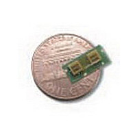
HPMD7904TR1 Avago Technologies US Inc., HPMD7904TR1 Datasheet - Page 7

HPMD7904TR1
Manufacturer Part Number
HPMD7904TR1
Description
Manufacturer
Avago Technologies US Inc.
Datasheet
1.HPMD7904TR1.pdf
(16 pages)
Specifications of HPMD7904TR1
Pin Count
3
Screening Level
Commercial
Lead Free Status / Rohs Status
Not Compliant
7
An additional set of nine thermal holes (copper filled)
may be added to remove heat from the Tx filter as
shown in Figure 16.
FBAR duplexers have extremely low thermal mass
and must be properly heat sunk, as well as isolated
from external sources of heat (such as a nearby power
amplifier). Failure to provide an adequate thermal
design to cool the duplexer may result in degrada-
tion of insertion loss at the high end of the Tx band,
or other performance problems.
RF Ground
Many of the same considerations which apply to the
thermal ground plane also apply to the RF ground
plane. A large area, as shown in Figure 3, provides
data sheet performance for the duplexer. In addition,
a series of 36 (or more) plated and plugged via holes
to a lower ground plane (0.35 to 0.40 mm in diam-
eter) should be provided around the perimeter of the
duplexer, as shown in Figure 16.
If a continuous ground plane cannot be provided on
the top surface of the motherboard, a ground patch
which extends 0.5 mm (or more) out from each side
of the duplexer can be used. However, in this case
the 36 (or more) plugged via holes connecting to a
lower level ground are essential for good performance.
In/out Connection Design
High isolation between ports is a characteristic of
Avago FBAR duplexers, and values often exceed
50 dB. In order for this performance to not be de-
graded by coupling within the user’s motherboard
will require 60dB or more of isolation between each
pair of the three input/output lines of that
motherboard. This is measured as shown in Figure
17, using copper pins to short out all three of the lines
to ground. Isolation is then measured between the
Tx, Rx and Ant lines, with 60 dB as a minimum
acceptable level.
Figure 17. Motherboard Isolation Test Method.
In order to achieve 60 dB of isolation in the
motherboard itself using microstrip transmission
lines, extreme care must be taken in the design due
to the poorly contained field lines in microstrip.
Ground areas between the lines and other good tech-
niques will have to be used. The use of coplanar
waveguide over a groundplane (CPWG) provides for
higher line-to-line isolation.
Design guidelines for CPWG transmission lines can
be found in AppCAD, the design/analysis software
found on the Web at http://www.semicon-
d u c t o r. a v a g o t e c h . c o m / c g i - b i n / m o r p h e u s /
wirelessDesignTool/utility.jsp?flag=App. Figure 18
provides the recommended dimensions for a CPWG
realization. Shown in the figure is a solder mask
(green) — this will be dealt with in detail below.
Better performance can be obtained using stripline,
where a buried conductor has aground plane on lay-
ers above and below. Such transmission lines have
excellent shielding, and line-to-line values in excess
of 80 dB can easily be achieved using this transmis-
sion line. The details of this transmission line real-
ization are shown in Figures 19 and 20. Small in/out
Figure 18. Recommended mounting for CPWG realization.


