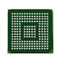
STM32F407IGH6 STMicroelectronics, STM32F407IGH6 Datasheet - Page 92

STM32F407IGH6
Manufacturer Part Number
STM32F407IGH6
Description
Microcontrollers (MCU) ARM M4 1024 FLASH 168 Mhz 192kB SRAM
Manufacturer
STMicroelectronics
Datasheet
1.STM32F407ZGT6.pdf
(167 pages)
Specifications of STM32F407IGH6
Core
ARM Cortex M4
Processor Series
STM32F4
Data Bus Width
32 bit
Maximum Clock Frequency
168 MHz
Program Memory Size
1024 KB
Data Ram Size
192 KB
On-chip Adc
Yes
Number Of Programmable I/os
140
Number Of Timers
10
Operating Supply Voltage
1.7 V to 3.6 V
Package / Case
UFBGA-176
Mounting Style
SMD/SMT
A/d Bit Size
12 bit
A/d Channels Available
24
Interface Type
CAN, I2C, I2S, SPI, UART
Program Memory Type
Flash
Lead Free Status / Rohs Status
Details
Available stocks
Company
Part Number
Manufacturer
Quantity
Price
Company:
Part Number:
STM32F407IGH6
Manufacturer:
STMicroelectronics
Quantity:
1
Company:
Part Number:
STM32F407IGH6
Manufacturer:
STMicroelectronics
Quantity:
10 000
Part Number:
STM32F407IGH6
Manufacturer:
ST
Quantity:
20 000
Electrical characteristics
5.3.11
Table 34.
1. Guaranteed by design, not tested in production.
92/167
MODEPER * INCSTEP
Symbol
f
md
Mod
PLL spread spectrum clock generation (SSCG) characteristics
The spread spectrum clock generation (SSCG) feature allows to reduce electromagnetic
interferences (see
SSCG parameters constraint
Equation 1
The frequency modulation period (MODEPER) is given by the equation below:
f
As an example:
If f
equation 1:
Equation 2
Equation 2 allows to calculate the increment step (INCSTEP):
f
With a modulation depth (md) = ±2 % (4 % peak to peak), and f
An amplitude quantization error may be generated because the linear modulation profile is
obtained by taking the quantized values (rounded to the nearest integer) of MODPER and
INCSTEP. As a result, the achieved modulation depth is quantized. The percentage
quantized modulation depth is given by the following formula:
As a result:
The error in modulation depth is consequently: 2.0 - 1.99954 = 0.00046%.
PLL_IN
VCO_OUT
PLL_IN
INCSTEP
and f
= 1 MHz, and f
must be expressed in MHz.
md
md
INCSTEP
Mod
quantized
quantized
must be expressed in Hz.
=
Table 40: EMI
round
%
%
=
MOD
=
[
round
=
(
Peak modulation depth
(
Modulation frequency
MODEPER
(
2
MODEPER
(
MODEPER INCSTEP
25
15
= 1 kHz, the modulation depth (MODEPER) is given by
Doc ID 022152 Rev 2
[
–
×
Parameter
(
(
1
1258
2
)
characteristics). It is available only on the main PLL.
15
×
–
2
×
1
×
=
) md
×
100
=
240
×
round 10
round f
×
)
⁄
5
(
×
100
)
[
[
f
⁄
VCO_OUT
(
PLL_IN
(
6
2
×
⁄
×
15
(
5
4
100
×
–
×
⁄
1
25
(
10
)
) 240
4
×
⁄
×
)
3
(
×
]
5
100 5
)
)
0.25
f
=
Min
]
Mod
⁄
STM32F405xx, STM32F407xx
-
-
(
=
1258md(quantitazed)%
(
)
×
2
25
)
VCO_OUT
=
15
]
×
1.99954%(peak)
–
MODEPER
1
Typ
) f
-
-
-
×
VCO_OUT
= 240 (in MHz):
Max
2
15
10
2
)
−1
]
(1)
)
Unit
KHz
%
-


