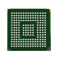
STM32F407IGH6 STMicroelectronics, STM32F407IGH6 Datasheet - Page 95

STM32F407IGH6
Manufacturer Part Number
STM32F407IGH6
Description
Microcontrollers (MCU) ARM M4 1024 FLASH 168 Mhz 192kB SRAM
Manufacturer
STMicroelectronics
Datasheet
1.STM32F407ZGT6.pdf
(167 pages)
Specifications of STM32F407IGH6
Core
ARM Cortex M4
Processor Series
STM32F4
Data Bus Width
32 bit
Maximum Clock Frequency
168 MHz
Program Memory Size
1024 KB
Data Ram Size
192 KB
On-chip Adc
Yes
Number Of Programmable I/os
140
Number Of Timers
10
Operating Supply Voltage
1.7 V to 3.6 V
Package / Case
UFBGA-176
Mounting Style
SMD/SMT
A/d Bit Size
12 bit
A/d Channels Available
24
Interface Type
CAN, I2C, I2S, SPI, UART
Program Memory Type
Flash
Lead Free Status / Rohs Status
Details
Available stocks
Company
Part Number
Manufacturer
Quantity
Price
Company:
Part Number:
STM32F407IGH6
Manufacturer:
STMicroelectronics
Quantity:
1
Company:
Part Number:
STM32F407IGH6
Manufacturer:
STMicroelectronics
Quantity:
10 000
Part Number:
STM32F407IGH6
Manufacturer:
ST
Quantity:
20 000
STM32F405xx, STM32F407xx
5.3.13
Table 37.
1. TBD stands for “to be defined”.
2. Guaranteed by design, not tested in production.
3. The maximum programming time is measured after 100K erase operations.
4. V
Table 38.
1. Based on characterization, not tested in production.
2. Cycling performed over the whole temperature range.
EMC characteristics
Susceptibility tests are performed on a sample basis during device characterization.
Functional EMS (electromagnetic susceptibility)
While a simple application is executed on the device (toggling 2 LEDs through I/O ports). the
device is stressed by two electromagnetic events until a failure occurs. The failure is
indicated by the LEDs:
●
●
Symbol
t
t
t
ERASE128KB
ERASE16KB
ERASE64KB
N
t
Symbol
RET
t
END
VPP
V
PP
t
V
Electrostatic discharge (ESD) (positive and negative) is applied to all device pins until
a functional disturbance occurs. This test is compliant with the IEC 61000-4-2 standard.
FTB: A burst of fast transient voltage (positive and negative) is applied to V
through a 100 pF capacitor, until a functional disturbance occurs. This test is compliant
with the IEC 61000-4-4 standard.
t
I
prog
ME
prog
PP
PP
should only be connected during programming/erasing.
(4)
Endurance
Data retention
Parameter
Flash memory programming with V
Flash memory endurance and data retention
Double word programming
Sector (16 KB) erase time
Sector (64 KB) erase time
Sector (128 KB) erase time
Mass erase time
Programming voltage
V
Minimum current sunk on
the V
Cumulative time during
which V
PP
voltage range
PP
PP
Parameter
pin
is applied
T
T
1 kcycle
1 kcycle
10 kcycles
A
A
= –40 to +105 °C (7 suffix versions)
= –40 to +85 °C (6 suffix versions)
Doc ID 022152 Rev 2
(2)
(2)
(2)
at T
at T
at T
Conditions
A
A
= 85 °C
= 105 °C
A
T
= 55 °C
A
Conditions
= 0 to +40 °C
PP
(1)
Min
2.7
10
7
-
-
-
-
-
-
Electrical characteristics
(1)
Value
Min
30
10
20
TBD
TBD
TBD
10
Typ
6.8
16
-
-
-
-
(1)
Max
100
DD
3.6
9
1
-
-
-
-
-
(3)
(2)
and V
kcycles
Years
Unit
95/167
Unit
hour
mA
µs
V
V
SS


