DS2174Q+ Maxim Integrated Products, DS2174Q+ Datasheet - Page 13
DS2174Q+
Manufacturer Part Number
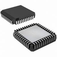
DS2174Q+
Description
IC BERT ENHANCED 44-PLCC
Manufacturer
Maxim Integrated Products
Datasheet
1.DS2174QTR.pdf
(24 pages)
Specifications of DS2174Q+
Function
Enhanced Bit Error Rate Tester (EBERT)
Interface
E1, J1, T1
Number Of Circuits
1
Voltage - Supply
3 V ~ 3.6 V
Current - Supply
50mA
Operating Temperature
0°C ~ 70°C
Mounting Type
Surface Mount
Package / Case
*
Includes
Error Counter, Pattern Generator and Detector
Lead Free Status / RoHS Status
Lead free / RoHS Compliant
Power (watts)
-


3.1 Mode Select
The DS2174 is configured to operate in bit, nibble, or byte mode by using the MODE1/MODE0 bits in
Control Register 2.
Table 3-A. Mode Select
3.1.1 Error Insertion
The DS2174 inserts bit errors at a particular rate by setting the error insertion bits in Control Register 2
(Table 3-B). In addition, the device inserts errors on command by setting the SBE bit in Control Register
2. The bit that occurs after the rising edge of the SBE insert bit is inverted. In the case of the QRSS
pattern, this could result in a string of 0’s longer than 14 bits; the DS2174 delays the erred bit by 1 clock
cycle.
Data in the nibble and byte modes is presented 4 or 8 bits at a time. When in nibble or byte mode and
selecting 10
selecting an error rate of 10
Table 3-B. Error Bit Insertion
EIR2
MODE1
0
0
0
0
1
1
1
1
0
0
1
1
EIR1
0
0
1
1
0
0
1
1
-1
MODE0
error rate, the device actually produces an error rate of 8
0
1
0
1
EIR0
0
1
0
1
0
1
0
1
-2
ERROR RATE
OPERATION MODE
, the device produces an error rate of 8
None
10
10
10
10
10
10
10
Invalid
Nibble
-1
-2
-3
-4
-5
-6
-7
Byte
Bit
13 of 24
SERIAL
4
4
4
4
4
4
4
4
NIBBLE
8
4
4
4
4
4
4
4
-2
-1
.
-1
. When in byte mode and
BYTE
8
8
4
4
4
4
4
4
-1
-2
Related parts for DS2174Q+
Image
Part Number
Description
Manufacturer
Datasheet
Request
R

Part Number:
Description:
EBERT
Manufacturer:
MAXIM [Maxim Integrated Products]
Datasheet:
Part Number:
Description:
Ds2174 Ebert
Manufacturer:
Maxim Integrated Products, Inc.
Datasheet:

Part Number:
Description:
MAX7528KCWPMaxim Integrated Products [CMOS Dual 8-Bit Buffered Multiplying DACs]
Manufacturer:
Maxim Integrated Products
Datasheet:
Part Number:
Description:
Single +5V, fully integrated, 1.25Gbps laser diode driver.
Manufacturer:
Maxim Integrated Products
Datasheet:
Part Number:
Description:
Single +5V, fully integrated, 155Mbps laser diode driver.
Manufacturer:
Maxim Integrated Products
Datasheet:
Part Number:
Description:
VRD11/VRD10, K8 Rev F 2/3/4-Phase PWM Controllers with Integrated Dual MOSFET Drivers
Manufacturer:
Maxim Integrated Products
Datasheet:
Part Number:
Description:
Highly Integrated Level 2 SMBus Battery Chargers
Manufacturer:
Maxim Integrated Products
Datasheet:
Part Number:
Description:
Current Monitor and Accumulator with Integrated Sense Resistor; ; Temperature Range: -40°C to +85°C
Manufacturer:
Maxim Integrated Products
Part Number:
Description:
TSSOP 14/A°/RS-485 Transceivers with Integrated 100O/120O Termination Resis
Manufacturer:
Maxim Integrated Products
Part Number:
Description:
TSSOP 14/A°/RS-485 Transceivers with Integrated 100O/120O Termination Resis
Manufacturer:
Maxim Integrated Products
Part Number:
Description:
QFN 16/A°/AC-DC and DC-DC Peak-Current-Mode Converters with Integrated Step
Manufacturer:
Maxim Integrated Products
Part Number:
Description:
TDFN/A/65V, 1A, 600KHZ, SYNCHRONOUS STEP-DOWN REGULATOR WITH INTEGRATED SWI
Manufacturer:
Maxim Integrated Products
Part Number:
Description:
Integrated Temperature Controller f
Manufacturer:
Maxim Integrated Products
Part Number:
Description:
SOT23-6/I°/45MHz to 650MHz, Integrated IF VCOs with Differential Output
Manufacturer:
Maxim Integrated Products
Part Number:
Description:
SOT23-6/I°/45MHz to 650MHz, Integrated IF VCOs with Differential Output
Manufacturer:
Maxim Integrated Products