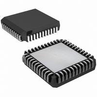
DS2174Q+ Maxim Integrated Products, DS2174Q+ Datasheet - Page 6

DS2174Q+
Manufacturer Part Number
DS2174Q+
Description
IC BERT ENHANCED 44-PLCC
Manufacturer
Maxim Integrated Products
Datasheet
1.DS2174QTR.pdf
(24 pages)
Specifications of DS2174Q+
Function
Enhanced Bit Error Rate Tester (EBERT)
Interface
E1, J1, T1
Number Of Circuits
1
Voltage - Supply
3 V ~ 3.6 V
Current - Supply
50mA
Operating Temperature
0°C ~ 70°C
Mounting Type
Surface Mount
Package / Case
*
Includes
Error Counter, Pattern Generator and Detector
Lead Free Status / RoHS Status
Lead free / RoHS Compliant
Power (watts)
-
1.5 Clock Discussion
There are two methods for moving test patterns through a telecom network.
1) The clock applied to TCLK and RCLK can be gapped by other devices on the target system. The
2) The clock applied to TCLK and RCLK can be continuous at the applicable line rate and the
1.6 Power-Up Sequence
On power-up, the registers in the DS2174 are in a random state. The user must program all the internal
registers to a known state before proper operation can be ensured.
Figure 1-1. Block Diagram
gapped clock would be applied to TCLK and RCLK only during the appropriate times. TDATn
outputs remain active during clock gaps.
TCLK_EN and RCLK_EN pins can be asserted and deasserted during the appropriate time slots.
TDATn outputs remain active even when TCLK_EN is pulled low. The output level remains static at
the level of the last bit transmitted (output high for a 1, output low for a 0).
SYNC
CR1.0
CR1.5
TL
LC
CS RD WR
PARALLEL CONTROL PORT
REPETITIVE PATTERN
GENERATOR
ERROR COUNTER
2
n
BIT COUNTER
- 1
A[3:0]
D[7:0]
PATTERN DETECTOR
6 of 24
ERROR INSERTION
TRANSMIT
CONTROL
CONTROL
RECEIVE
RATE
RATE
RCLK_EN
RCLK
RDAT[7:0]
TCLK_EN
TCLK
TDAT[7:0]
TCLK0


