TDA7496 STMicroelectronics, TDA7496 Datasheet
TDA7496
Specifications of TDA7496
TDA7496
Available stocks


Related parts for TDA7496


TDA7496 Summary of contents
Page 1
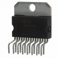
... NO ST_BY RC INPUT NETWORK SINGLE SUPPLY RANGING UP TO 35V SHORT CIRCUIT PROTECTION THERMAL OVERLOAD PROTECTION INTERNALLY FIXED GAIN SOFT CLIPPING VARIABLE OUTPUT AFTER VOLUME CONTROL CIRCUIT MULTIWATT 15 PACKAGE DESCRIPTION The TDA7496 is a stereo 5+5W class AB power am- BLOCK DIAGRAM PW_GND 11 1 INR 470nF 30K S_GND 8 ...
Page 2
... TDA7496 ABSOLUTE MAXIMUM RATINGS Symbol V DC Supply Voltage S V Maximum Input Voltage IN P Total Power Dissipation (T tot T Ambient Operating Temperature (1) amb T ,T Storage and Junction Temperature stg J V Volume Control DC Voltage 3 PIN CONNECTION (top view) THERMAL DATA Symbol R Thermal Resistance junction-case ...
Page 3
... MUTE f = 1KHz; max volume C = 470 1Vrms SVR RIP f = 1KHz; max attenuation C = 470 1Vrms SVR RIP Stand by ON 5V; ST- mute Play or Mute Mute Play TDA7496 Min. Typ. Max. Unit 1.0 1.3 A 2.8 Vrms 28.5 30 31.5 dB -1 0.6 MHz 500 ...
Page 4
... TDA7496 APPLICATION SUGGESTIONS The recommended values of the external components are those shown on the application circuit of figure 1. Different values can be used, the following table can help the designer. SUGGESTION COMPONENT VALUE R1 300K R2 10K P1 50K C1 1000 F C2 470nF C3 470nF C4 470 F C5 100nF C6 1000 F ...
Page 5
... At the turn-on the transition mute to mute - play must be made when the SVR pin is higher than 2.5V – At the turn-off the TDA7496 must be brought to mute from the play condition when the SVR pin is higher than 2.5V. ...
Page 6
... TDA7496 Figure 2. P.C.B. and Component layoutPCB and Component Layout Figure 3. 6/11 ...
Page 7
... Figure 9. Distortion vs Output Power D03AU1497 Distortion (%) 1 0.1 THD= Supply Voltage (V) Rl=4 F=1KHz THD=10% 10 10.5 11 11.5 12 12.5 Supply Voltage (V) Vs=22V Rl=8 F=15KHz F=1KHz 0 0.5 1.0 1.5 2.0 2.5 3.0 3.5 4.0 4.5 5.0 5.5 Output Power (W) TDA7496 D03AU1496 D03AU1498 THD=1% 13 13.5 14 D03AU1499 7/11 ...
Page 8
... TDA7496 Figure 10. Distortion vs Output Power Distortion (%) F=15KHz 1 0.1 F=1KHz 0.01 0 0.2 0.4 0.6 0.8 1.0 1.2 1.4 1.6 1.8 2.0 Output Power (W) Figure 11. Closed Loop Gain vs. Frequency Closed loop Gain (dB 0.02 0.2 Frequency (KHz) Figure 12. St-By Attenuation vs Vpin 9 St-by Attenuation (dB) ...
Page 9
... Figure 17. PIN ST-BY STBY 200 65K D97AU594 Figure 18. PIN: MUTE MUTE 200 10K D97AU592 Figure 19. PINS: OUT R, OUT L OUT D97AU588 Figure 20. PINS: VAROUT-L VAROUT Figure 21. PIN: VOLUME Figure 22. PINS: PW-GND, S-GND TDA7496 V S VAROUT-L D97AU590 VOL D97AU591 V S GND D97AU593 9/11 ...
Page 10
... TDA7496 mm DIM. MIN. TYP. MAX 2. 0.49 0.55 0.019 F 0.66 0.75 0.026 G 1.02 1.27 1.52 0.040 G1 17.53 17.78 18.03 0.690 H1 19.6 0.772 H2 20.2 L 21.9 22.2 22.5 0.862 L1 21.7 22.1 22.5 0.854 L2 17.65 18.1 0.695 L3 17.25 17.5 17.75 0.679 L4 10.3 10.7 10 ...
Page 11
... Australia - Belgium - Brazil - Canada - China - Czech Republic - Finland - France - Germany - Hong Kong - India - Israel - Italy - Japan - Malaysia - Malta - Morocco - Singapore - Spain - Sweden - Switzerland - United Kingdom - United States All other names are the property of their respective owners © 2003 STMicroelectronics - All rights reserved STMicroelectronics GROUP OF COMPANIES www.st.com TDA7496 11/11 ...