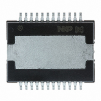
TDF8590TH/N1,118 NXP Semiconductors, TDF8590TH/N1,118 Datasheet - Page 18

TDF8590TH/N1,118
Manufacturer Part Number
TDF8590TH/N1,118
Description
IC AMP AUDIO PWR 160W D 24HSOP
Manufacturer
NXP Semiconductors
Type
Class Dr
Datasheet
1.TDF8590THN1S118.pdf
(30 pages)
Specifications of TDF8590TH/N1,118
Output Type
1-Channel (Mono) or 2-Channel (Stereo)
Package / Case
24-HSOP
Max Output Power X Channels @ Load
160W x 1 @ 8 Ohm; 80W x 2 @ 4 Ohm
Voltage - Supply
±14 V ~ 29 V
Features
Depop, Differential Inputs, Mute, Short-Circuit and Thermal Protection, Standby
Mounting Type
Surface Mount
Product
Class-D
Output Power
160 W
Available Set Gain
32 dB
Common Mode Rejection Ratio (min)
75 dB
Thd Plus Noise
0.15 %
Maximum Operating Temperature
+ 85 C
Mounting Style
SMD/SMT
Audio Load Resistance
8 Ohms
Dual Supply Voltage
+/- 27 V
Input Signal Type
Differential
Minimum Operating Temperature
- 40 C
Output Signal Type
Differential, Single
Supply Type
Dual
Lead Free Status / RoHS Status
Lead free / RoHS Compliant
Other names
935278835118
TDF8590TH/N1-T
TDF8590TH/N1-T
TDF8590TH/N1-T
TDF8590TH/N1-T
NXP Semiconductors
TDF8590TH_2
Product data sheet
12.7 Application schematics
The pumping effect should not cause a malfunction of either the audio amplifier and/or the
voltage supply source. For instance, this malfunction can be caused by triggering of the
UVP, OVP or UBP of the amplifier. Best remedy for pumping effects is to use the
TDF8590TH in a mono full-bridge application. In case of dual half-bridge application adapt
the power supply (e.g. increase supply decoupling capacitors).
For SE application (see
For BTL application (see
•
•
•
•
•
•
•
•
•
•
•
•
A solid ground plane around the TDF8590TH is necessary to prevent emission
100 nF SMD capacitors must be placed as close as possible to the power supply pins
of the TDF8590TH
The heatsink of the HSOP24 package of the TDF8590TH is connected to pin V
The external heatsink must be connected to the ground plane
Use a thermal conductive, electrically isolating Sil-Pad between the backside of the
TDF8590TH and the external heatsink
The differential inputs enable the best system level audio performance with
unbalanced signal sources. In case of hum due to floating inputs connect the
shielding or source ground to the amplifier ground. The jumper J1 is open on set level
and is closed on the stand-alone demo board
Minimum total required capacity per power supply line is 3300 F
Rev. 02 — 23 April 2007
Figure
Figure
2
10):
80 W SE (4 ) or 1
11):
160 W BTL (8 ) class-D amplifier
TDF8590TH
© NXP B.V. 2007. All rights reserved.
18 of 30
SSD
SSD


