TDA7297D STMicroelectronics, TDA7297D Datasheet
TDA7297D
Specifications of TDA7297D
Available stocks


Related parts for TDA7297D


TDA7297D Summary of contents
Page 1
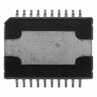
... R1 47K JP1 +5V R2 47K ST-BY MUTE May 2004 10W+10W DUAL BRIDGE AMPLIFIER Figure 1. Package Table 1. Order Codes Part Number TDA7297D 2 DESCRIPTION The TDA7297D is a dual bridge amplifier specially designed for Home Audio, Plasma TV, LCD TV appli- cations 0. IN1 + - S-GND 13 R3 10K Vref + C5 0 ...
Page 2
... TDA7297D Table 2. Absolute Maximum Ratings Symbol V Supply Voltage s I Output Peak Current (internally limited Total Power Dissipation (T tot T Operating Temperature Storage and Junction Temperature stg, j Table 3. Thermal Data Symbol R Thermal Resistance Junction-case th j-case Figure 3. PIN CONNECTION PW GND OUT2+ N.C. N.C. OUT2- ...
Page 3
... Noise" on the speakers. A delay of 100-200ms between St-by and mute signals is suitable for a proper operation. = 13V 1KHz Test Condition THD 10 0. 100Hz to 15KHz f = 100Hz, VR =0. -30dB A Curve f = 20Hz to 20KHz TDA7297D = 25°C unless otherwise amb Min. Typ. Max. Unit 6 120 mV 8 0.1 0 ...
Page 4
... TDA7297D Figure 4. Microprocessor Application IN1 ST-BY P IN2 MUTE Figure 5. Microprocessor Driving Signals +V (V) S +13V V IN (mV) V ST-BY pin 9 1.8 1.3 0.8 V MUTE pin 8 4.1 2.9 2 (mA) V OUT (V) OFF 4/ 10K S-GND 13 - Vref + C3 0. 10K PW-GND 20 + PLAY MUTE ST-BY MUTE V CC ...
Page 5
... Rl= 8ohm 0.5 0.2 0.1 0.05 0.02 0. 100 200 500 Frequency (Hz) Figure 9. Frequency Response L evel . . . . . . . . . . Figure 10. Output Power vs supply Voltage Figure 11. Power Dissipation vs Pout 10k freq uency ( =8ohm Rl =8ohm F=1KHz F=1KHz d=10% d=10 d=1% d= (V) Vs (V) Vcc=13V ohm F=1KHz 2xPout(W) TDA7297D 5/11 ...
Page 6
... TDA7297D Figure 12. Mute Attenuation vs. Vpin 8t Attenuation (dB -10 -20 -30 -40 -50 -60 -70 -80 -90 -100 1 1.5 2 2.5 3 Vpin.6(V) Figure 13. Standard-By Attenuation vs Vpin. 9 Attenuation (dB -10 -20 -30 -40 -50 -60 -70 -80 -90 -100 -110 -120 0 0.2 0.4 0.6 0.8 1 1.2 1.4 Vpin.7 (V) 6/11 Figure 14. Quiescent Curent vs. Supply Voltage ...
Page 7
... Figure 15. PC Board Component Layout Figure 16. Evaluation Board Top Layer Layout Sign GND TDA7297D 7/11 ...
Page 8
... TDA7297D Figure 17. Evaluation Board Bottom Layer Layout 8/11 ...
Page 9
... DETAIL A D2 (x2 Gage Plane D1 11 PSO20DME D OUTLINE AND MECHANICAL DATA PowerSO20 (SLUG UP DETAIL A 0. SEATING PLANE (COPLANARITY) 0088529 C TDA7297D 9/11 ...
Page 10
... TDA7297D Table 5. Revision History Date Revision May 2004 10/11 1 First Issue Description of Changes ...
Page 11
... TDA7297D Information furnished is believed to be accurate and reliable. However, STMicroelectronics assumes no responsibility for the consequences of use of such information nor for any infringement of patents or other rights of third parties which may result from its use. No license is granted by implication or otherwise under any patent or patent rights of STMicroelectronics. Specifications mentioned in this publication are subject to change without notice ...