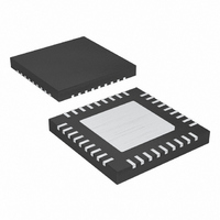
MAX9742ETX+ Maxim Integrated Products, MAX9742ETX+ Datasheet - Page 24

MAX9742ETX+
Manufacturer Part Number
MAX9742ETX+
Description
IC AMP AUDIO PWR 20.5W D 36TQFN
Manufacturer
Maxim Integrated Products
Type
Class Dr
Datasheet
1.MAX9742ETX.pdf
(36 pages)
Specifications of MAX9742ETX+
Output Type
2-Channel (Stereo)
Max Output Power X Channels @ Load
20.5W x 2 @ 8 Ohm
Voltage - Supply
20 V ~ 40 V, ±10 V ~ 20 V
Features
Depop, Differential Inputs, Mute, Short-Circuit and Thermal Protection, Shutdown
Mounting Type
Surface Mount
Package / Case
36-TQFN Exposed Pad
Product
Class-D
Output Power
16 W
Thd Plus Noise
0.08 %
Supply Current
15 mA
Maximum Power Dissipation
2.86 W
Maximum Operating Temperature
+ 85 C
Mounting Style
SMD/SMT
Audio Load Resistance
4 Ohms
Minimum Operating Temperature
- 40 C
Lead Free Status / RoHS Status
Lead free / RoHS Compliant
Single-/Dual-Supply, Stereo 16W,
Class D Amplifier with Differential Inputs
A multiple-pole MID network improves PSRR perfor-
mance over a single-pole network. Since the input
amplifiers of the MAX9742 are biased at V
noise coupled into the MID input using the MID bias
network supply appears at the outputs of the MAX9742.
Increasing the number of poles in the MID network pro-
vides further attenuation of low-frequency noise at the
MID input, and therefore, improving the AC PSRR per-
formance of the MAX9742. Figure 11 shows the recom-
mended single-pole and two-pole MID input bias
networks. Figure 12 illustrates the differences of the
MAX9742’s low-frequency AC PSRR performance with
the single-pole and two-pole networks shown in Figure
11.
Figure 11. Recommended MID Input Bias Networks
24
______________________________________________________________________________________
Single-Pole VMID Network for Increased PSRR
10kΩ
10kΩ
10kΩ
10kΩ
R1
R2
R1
R2
Performance (Single-Supply Operation)
V
V
DD
DD
SINGLE-POLE NETWORK
TWO-POLE NETWORK
C
22µF
C
10µF
Multiple-Pole MID Network vs.
MID1
MID1
10kΩ
R3
C
1µF
C
10µF
MID2
MID2
TO
MID
TO
MID
MID
, any
The soft-start capacitor determines the timing for the
soft-start power-up sequencing that minimizes audible
clicks-and-pops during power-up/power-down transi-
tions and when entering/exiting shutdown mode.
Connect a capacitor between SFT and ground for
proper operation. For optimum performance, this
capacitor should equal 0.22µF. Using capacitor values
much smaller than these values degrade click-and-
pop performance and values much greater lengthen
startup time.
At the beginning of the soft-start sequence, the
MAX9742 ensures V
V
gle-supply operation with single-ended outputs, the
output-coupling capacitors (C
charged up to V
sequencing. This gradual charging up of C
mizes audible transients that may appear across the
Figure 12. Comparison of MAX9742 AC PSRR with Single-Pole
and Two-Pole MID Networks
MID
before continuing the soft-start sequence. For sin-
-100
-120
-20
-40
-60
-80
20
0
10
SINGLE SUPPLY
V
R
POWER-SUPPLY REJECTION RATIO
DD
L
2-POLE MID NETWORK
= 8Ω
= 24V + 500mV
MID
100
OUT_
1-POLE MID NETWORK
vs. FREQUENCY
before continuing soft-start
FREQUENCY (Hz)
Startup Time Considerations
P-P
Soft-Start Capacitor (C
is approximately equal to
1k
OUT
) are first gradually
10k
100k
OUT
mini-
SFT
)


