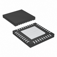
MAX9742ETX+ Maxim Integrated Products, MAX9742ETX+ Datasheet - Page 25

MAX9742ETX+
Manufacturer Part Number
MAX9742ETX+
Description
IC AMP AUDIO PWR 20.5W D 36TQFN
Manufacturer
Maxim Integrated Products
Type
Class Dr
Datasheet
1.MAX9742ETX.pdf
(36 pages)
Specifications of MAX9742ETX+
Output Type
2-Channel (Stereo)
Max Output Power X Channels @ Load
20.5W x 2 @ 8 Ohm
Voltage - Supply
20 V ~ 40 V, ±10 V ~ 20 V
Features
Depop, Differential Inputs, Mute, Short-Circuit and Thermal Protection, Shutdown
Mounting Type
Surface Mount
Package / Case
36-TQFN Exposed Pad
Product
Class-D
Output Power
16 W
Thd Plus Noise
0.08 %
Supply Current
15 mA
Maximum Power Dissipation
2.86 W
Maximum Operating Temperature
+ 85 C
Mounting Style
SMD/SMT
Audio Load Resistance
4 Ohms
Minimum Operating Temperature
- 40 C
Lead Free Status / RoHS Status
Lead free / RoHS Compliant
speaker loads during mode transitions. After C
charged up to V
start sequence by precharging C
C
MAX9742 begins normal operation.
For dual-supply operation, the startup time of the
MAX9742 is primarily dependent on the value of C
since it controls the rate of the soft-start sequencing.
In single-supply operation, the overall startup time is
affected by the values of C
(single-ended outputs) and the value of the resistors
used to bias the MID input. This is because soft-start
power-up sequencing is dependent on the charging-up
of the MID input bias network and the charging rate of
C
also affected by the value of C
rate of the soft-start sequencing. Using the component
values shown in Figure 11 and a C
of 0.22µF yields a typical single-supply power-up time
of 1.5s.
For single-supply operation with single-ended outputs,
the leakage current of C
time of the MAX9742. To minimize startup time delays
due to C
ings less than 1µA for C
IN
OUT
. Once the soft-start sequence is complete, the
. As with dual-supply operation, the startup time is
OUT
, use capacitors with leakage current rat-
MID
Class D Amplifier with Differential Inputs
______________________________________________________________________________________
, the MAX9742 concludes the soft-
OUT
OUT
.
MID1
can also affect the startup
SFT
, C
REGLS
since it controls the
SFT
MID2
Single-/Dual-Supply, Stereo 16W,
capacitor value
, C
, C
BOOT
SFT
, C
OUT
, and
OUT
SFT
is
When using the MAX9742 in the single-ended output
configuration, the power-supply voltages (V
V
This “supply pumping” is primarily due to the inductive
loading of the LC filter and the voice coil inductance of
the speaker. The inductive load connected to the out-
put of the device prevents the output current from
changing instantaneously. When the MAX9742 drives
this inductive load, a continuous current flows at the
output whose value is equal to the running average of
the output switching currents, or in other words, the
amplified audio signal. This averaged current continues
to flow during both switching cycles of the half-bridge,
which means that some of the current is pumped back
towards the opposite power supply. If the respective
supply cannot sink this current, it flows into supply
bypass capacitor causing the voltage across the
capacitor to increase.
The amount of current pumped back into the opposite
supply is proportional to the duty cycle of the switching
period. For example, if the magnitude of the average
(continuous) current during a single switching cycle is
equal to -1A and the duty cycle of the output is equal to
25%, this means the V
rent while the V
V
bypass capacitor causing the V
pumped up. Figures 13a and 13b illustrates the contin-
uous output current flow that causes the supply pump-
ing action.
SS
DD
) may increase if the supplies cannot sink current.
supply cannot sink this current, it flows into the
DD
supply must sink 0.25A. Since the
SS
supply provides 0.75A of cur-
Supply Pumping Effects
DD
supply voltage to be
DD
and
25


