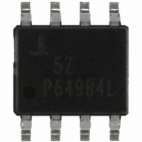
HA9P5020-5Z Intersil, HA9P5020-5Z Datasheet

HA9P5020-5Z
Specifications of HA9P5020-5Z
Available stocks
Related parts for HA9P5020-5Z
HA9P5020-5Z Summary of contents
Page 1
... CAUTION: These devices are sensitive to electrostatic discharge; follow proper IC Handling Procedures. 1-888-INTERSIL or 1-888-468-3774 All other trademarks mentioned are the property of their respective owners. HA-5020 June 5, 2006 FN2845.11 | Intersil (and design registered trademark of Intersil Americas Inc. Copyright Intersil Americas Inc. 2002, 2005-2006. All Rights Reserved ...
Page 2
... HA9P5020-5X96 50205 HA9P5020-5ZX96 (Note) 50205Z NOTE: Intersil Pb-free plus anneal products employ special Pb-free material sets; molding compounds/die attach materials and 100% matte tin plate termination finish, which are RoHS compliant and compatible with both SnPb and Pb-free soldering operations. Intersil Pb-free products are MSL classified at Pb-free peak reflow temperatures that meet or exceed the Pb-free requirements of IPC/JEDEC J STD-020 ...
Page 3
Absolute Maximum Ratings (Note 1) Voltage Between V+ and V- Terminals . . . . . . . . . . . . . . . . . . . 36V DC Input Voltage . . . . . . ...
Page 4
... Rise Time (Note 8) Fall Time (Note 8) Propagation Delay (Notes 8, 14) -3dB Bandwidth Settling Time to 1% Settling Time to 0.1% INTERSIL VALUE ADDED SPECIFICATIONS Input Noise Voltage (Note 14) +Input Noise Current (Note 14) -Input Noise Current (Note 14) Input Common Mode Range -I Adjust Range (Note 3) ...
Page 5
Electrical Specifications V SUPPLY Unless Otherwise Specified (Continued) PARAMETER Output Current, Short Circuit (Note 14) Output Current, Disabled (Note 14) Output Disable Time (Notes 10, 14) Output Enable Time (Notes 11, 14) Supply Voltage Range Output Capacitance, Disabled (Note 12) ...
Page 6
Electrical Specifications V+ = +5V -5V, R Parameters are not tested. The limits are guaranteed based on lab characterizations, and reflect lot-to-lot variation. (Continued) PARAMETER Open Loop DC Voltage Gain OUTPUT CHARACTERISTICS Output Voltage Swing (Note 14) Output ...
Page 7
... Parameters are not tested. The limits are guaranteed based on lab characterizations, and reflect lot-to-lot variation. (Continued) PARAMETER -3dB Bandwidth (Note 14) Settling Time to 1% Settling Time to 0.25% INTERSIL VALUE ADDED SPECIFICATIONS Input Noise Voltage (Note 14) +Input Noise Current (Note 14) -Input Noise Current (Note 14) Input Common Mode Range Output Current, Short Circuit ...
Page 8
Test Circuits and Waveforms FIGURE 1. TEST CIRCUIT FOR TRANSIMPEDANCE MEASUREMENTS DUT 50Ω 1kΩ F FIGURE 2. SMALL SIGNAL PULSE RESPONSE CIRCUIT OUT Vertical Scale 100mV/Div Horizontal ...
Page 9
Schematic Diagram 9 HA-5020 FN2845.11 June 5, 2006 ...
Page 10
Application Information Optimum Feedback Resistor The plots of inverting and non-inverting frequency response illustrate the performance of the HA-5020 in various closed loop gain configurations. Although the bandwidth dependency on closed loop gain isn’t as severe as that of a ...
Page 11
Referring to Figure 7, it can be seen that R resistor the DISABLE pin is left open. In those cases CC where the enable/disable function is not required on all circuits some circuits can be permanently enabled ...
Page 12
INPUT B INPUT CHANNEL SWITCH U 1A INHIBIT R 6 100K Typical Performance Curves 100 A = +10 V -INPUT NOISE CURRENT 10 INPUT NOISE VOLTAGE +INPUT NOISE CURRENT 1 10 100 1k FREQUENCY (Hz) FIGURE ...
Page 13
Typical Performance Curves ±15V V SUPPLY = ±10V V SUPPLY -60 -40 - TEMPERATURE (°C) FIGURE 13. TRANSIMPEDANCE vs TEMPERATURE (AVERAGE OF 30 UNITS FROM 3 LOTS) 7 DISABLE ...
Page 14
Typical Performance Curves 2.0 1.8 1.6 1.4 1.2 1.0 ENABLE TIME 0.8 0.6 0.4 DISABLE TIME 0.2 0.0 - OUTPUT VOLTAGE (V) FIGURE 19. ENABLE/DISABLE TIME vs OUTPUT VOLTAGE (AVERAGE OF 9 UNITS FROM ...
Page 15
Typical Performance Curves 100 C = 10pF 0.2V OUT GAIN PEAKING 80 400 600 800 FEEDBACK RESISTOR (Ω) FIGURE 25. BANDWIDTH AND GAIN PEAKING vs FEEDBACK RESISTANCE -60 ...
Page 16
Typical Performance Curves 100 90 80 -ISC 70 +ISC -60 -40 - TEMPERATURE (°C) FIGURE 31. SHORT CIRCUIT CURRENT LIMIT vs TEMPERATURE 11.0 10.0 9.0 8.0 7 100Ω LOAD 6.0 V ...
Page 17
Typical Performance Curves 0.07 0.06 0.05 0.04 0.03 0. LOAD 0. SUPPLY VOLTAGE (±V) FIGURE 37. DIFFERENTIAL PHASE vs SUPPLY VOLTAGE (AVERAGE OF 18 UNITS FROM 3 LOTS) Typical Performance Curves 5 4 ...
Page 18
Typical Performance Curves 100 95 -3dB BANDWIDTH 90 GAIN PEAKING 350 500 650 800 FEEDBACK RESISTOR (Ω) FIGURE 43. BANDWIDTH AND GAIN PEAKING vs FEEDBACK RESISTANCE 200 350 500 650 FEEDBACK RESISTOR (Ω) FIGURE 45. ...
Page 19
Typical Performance Curves 0 0.2V 0.6 OUT P 10pF L 0 -0.2 -0 1kΩ -0 ...
Page 20
Typical Performance Curves DISABLE = P 750Ω F -10 -20 -30 -40 -50 -60 -70 -80 0.1M 1M FREQUENCY (Hz) FIGURE 55. DISABLE FEEDTHROUGH vs FREQUENCY 20 HA-5020 = ±5V ...
Page 21
Die Characteristics DIE DIMENSIONS: 1640µm x 1520µm x 483µm METALLIZATION: Type: Aluminum, 1% Copper ±2k Å Å Thickness: 16k SUBSTRATE POTENTIAL (Powered Up): V- Metallization Mask Layout BAL 2 IN- 3 IN+ 21 HA-5020 PASSIVATION: Type: Nitride over Silox Silox ...
Page 22
Dual-In-Line Plastic Packages (PDIP INDEX N/2 AREA -B- -A- D BASE PLANE -C- SEATING PLANE 0.010 (0.25 NOTES: 1. Controlling Dimensions: INCH. In case of conflict between ...
Page 23
... Accordingly, the reader is cautioned to verify that data sheets are current before placing orders. Information furnished by Intersil is believed to be accurate and reliable. However, no responsibility is assumed by Intersil or its subsidiaries for its use; nor for any infringements of patents or other rights of third parties which may result from its use ...


