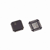
EL4543ILZ Intersil, EL4543ILZ Datasheet - Page 12

EL4543ILZ
Manufacturer Part Number
EL4543ILZ
Description
IC DRIVER TWISTED 350MHZ 20QFN
Manufacturer
Intersil
Datasheet
1.EL4543IUZ.pdf
(18 pages)
Specifications of EL4543ILZ
Applications
Driver
Output Type
Differential
Number Of Circuits
3
-3db Bandwidth
350MHz
Slew Rate
1000 V/µs
Current - Supply
14.5mA
Current - Output / Channel
60mA
Voltage - Supply, Single/dual (±)
5 V ~ 12 V, ±2.5 V ~ 6 V
Mounting Type
Surface Mount
Package / Case
20-VQFN Exposed Pad, 20-HVQFN, 20-SQFN, 20-DHVQFN
Rohs Compliant
YES
Lead Free Status / RoHS Status
Lead free / RoHS Compliant
Available stocks
Company
Part Number
Manufacturer
Quantity
Price
Company:
Part Number:
EL4543ILZ
Manufacturer:
Intersil
Quantity:
2 195
Part Number:
EL4543ILZ
Manufacturer:
INTERSIL
Quantity:
20 000
Part Number:
EL4543ILZ-T13
Manufacturer:
INTERSIL
Quantity:
20 000
Extract Common Mode Sync and Decode H
and V
H
Mode sync output voltages. The relationships between
H
Table 1. The common mode levels are easily separated from
the differential outputs of the EL4543 using this simple
resistor network at the cable receiver input of each
differential channel; see Figure 39.
Twisted Pair Termination
The schematic in Figure 39 illustrates a termination scheme for
50Ω series termination and a 100Ω twisted pair cable. Note
RCM is the common mode termination to allow measurement
of V
little over a 100Ω is recommended for RCM.
Video Transmission
The EL4543 is a twisted pair differential line driver directed at
the transmission of Video Signals through cables up to 100
feet; however, as signal losses increase with transmission line
length the EL4543 will need additional support to equalize
video signals along longer twisted pair transmission lines. A
full solution to accomplish this is the SXGA Video
Transmission System presented in the EL4543 Data Sheet.
Note the inclusion of the EL9110 for signal equalization of up
to 1000ft of CAT5 cable and common mode extraction; see
Data Sheet for additional information on the EL9110.
Long Distance Video Transmission
The SXGA Video Transmission System makes it possible to
transmit Red, Green and Blue (RGB) video plus sync up to
1000 feet through CAT5 cable. The input to the SXGA Video
Transmission System is the output of a video source
transmitting RGB video signals plus sync. The signals are
received initially by the EL4543; which converts the single
ended input RGB signals to three fully differential waveforms
with sync encoded on the discrete common modes of each
color channel and then drives the signals through a length of
CAT5 cable. The signal is received by the EL9110, which
can provide 6-pole equalization for both high and low
frequency signal transmission line losses. Then the EL9110
converts the differential RGB video signals back into single
ended format while extracting the common mode component
for decoding. The single ended RGB signal is taken directly
from the output of the El9110 and is ready for the output
device. The Common Mode Decoder Circuit receives the
common mode signals directly from each of the three
TYPICAL EL4543 TERMINATION DRIVER
V
SYNC
SYNC
REF
+
-
CM
FIGURE 39. TWISTED PAIR TERMINATION EL4543
SYNC
, V
and should not be too small since it loads the EL4543; a
and V
50Ω
50Ω
SYNC
SYNC
Z
TWISTED
and the 3 common mode levels are given by
O
=100Ω
PAIR
can be regenerated from the Common
12
50Ω
50Ω
+
-
120Ω
(RCM: SHOULD BE >100Ω)
(FOR LOADING
CONSIDERATIONS)
V
CM
SYNC
EL4543
EL9110's common mode output pin, decodes and transmits
H
Sync Transmission
The EL4543 encodes H
common mode output of the differential video signals; Red,
Green and Blue respectively. Data Sheet Figure 8 clearly
illustrates that the sum of the common mode voltages results
in a fixed DC level with no AC content; thus eliminating EMI
interference.
Output Drive Protection
The EL4543 has internal short circuit protection set typically
at 60mA. if the output is shorted for extended periods of time
the increased power dissipation will eventually destroy the
part. To realize maximum reliability the output current should
never exceed 60mA. The 50Ω series back load matching
resistor provides additional protection.
Supply Voltage
While the EL4543 can be operated on ±5V split rails, single
supply 0V to 5V is the most common usage. It is very
important to note that the input logic thresholds are relative
to the negative supply pin, and therefore single supply,
ground referenced logic will not work when driving the
EL4543 on split rails. The amplifiers have an input common
mode range from 0V to 2.3V with a 0V to 5V supply,
increasing with supply voltage (see Figure 7). The common
mode output DC level range is a linear function of the power
supply (see Figures 16, 17, 18, and 19). The common mode
input switching threshold as well as the Enable/Disable input
is a linear function of the supply voltage (see Figures 8 and
11). In the event that the EL4543 is to be used with ±5V split
rails then the input sync signals need to be voltage offset
before they are input to the EL4543. The circuit configuration
depicted in Figure 40 provides for the proper level shift.
SYNC
FIGURE 40. LEVEL SHIFTING SYNC SIGNALS FOR USE
Horizontal Sync in
Vertical Sync in
and V
SYNC
WITH ±5V SPLIT RAILS
to the output device.
4.30k
4.30k
SYNC
KST2907A
KST2907A
and V
SYNC
-5V
-5V
2.70k
2.70k
signals onto the
September 13, 2007
HSYN Pin
VSYN Pin
EL4543
EL4543
FN7325.11


