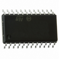
STA020D STMicroelectronics, STA020D Datasheet - Page 3

STA020D
Manufacturer Part Number
STA020D
Description
IC TRANSMITTER AUD 96KHZ 24SOIC
Manufacturer
STMicroelectronics
Type
Digital Audio Interface Transmitterr
Datasheet
1.STA020D.pdf
(14 pages)
Specifications of STA020D
Mounting Type
Surface Mount
Package / Case
24-SOIC (7.5mm Width)
Operating Supply Voltage (typ)
3.3V
Operating Supply Voltage (min)
3V
Operating Supply Voltage (max)
3.6V
Operating Temp Range
0C to 70C
Operating Temperature Classification
Commercial
Mounting
Surface Mount
Pin Count
24
Lead Free Status / RoHS Status
Lead free / RoHS Compliant
Applications
-
Lead Free Status / Rohs Status
Compliant
Other names
497-3941-5
Available stocks
Company
Part Number
Manufacturer
Quantity
Price
Company:
Part Number:
STA020D
Manufacturer:
ROHM
Quantity:
3 122
Part Number:
STA020D
Manufacturer:
ST
Quantity:
20 000
Part Number:
STA020DJTR
Manufacturer:
ST
Quantity:
20 000
PIN DESCRIPTION (continued)
Control Pins
22,23
21,
N°
10
11
12
13
14
15
16
7
8
1
2
3
4
9
M0, M1, M2
CBL/SBC
EM1/C8
EM0/C9
C1/FC0
FSYNC
C9/C15
SDATA
C/SBF
C7/C3
C6/C2
PRO
RST
Pin
V
U
Frame Sync.
Delineates the serial data and may indicate the particular channel, left or right and may be
an input or output. The format is based on M0, M1 and M2 pins.
Serial Data.
Audio data serial input pin.
Serial Port Mode Select.
Selects the format of FSYNC and the sample edge of SCK with respect to SDATA.
Channel Status Bit 7/Channel Status Bit 3
In professional mode, C7 is the inverse of channel status bit 7. In consumer mode, C3 is the
inverse of channel status bit 3, C7/C3 are ignored in Transparent Mode.
Professional/Consumer Select.
Selects between professional mode (PRO low) and consumer mode (PRO high). This pin
defines the functionality of the channel status parallel pins. PRO is ignored in Transparent
Mode.
Channel Status Bit 1/Frequency Control 0.
In professional mode, C1 is the inverse of channel status bit 1. In consumer mode, FC0 and
FC1 are encoded versions of channel status bits 24 and 25 (bits 0 and 1 of byte 3). When
FC0 and FC1 are both high, CD mode is selected. C1/FC0 are ignored in Transparent
Mode.
Channel Status Bit 6/Channel Status Bit 2.
In professional mode, C6 is the inverse of channel status bit 6. In consumer mode, C2 is the
inverse of channel status bit 2. C6/C2 are ignored in Transparent Mode
Validity.
Validity bit serial input port. This bit is defined as per the digital audio standards wherein V =
0 signifies the audio signal is suitable for conversion to analog. V = 1 signifies the audio
signal is not suitable for conversion to analog, i.e. invalid.
Channel Status Serial Input/Subcode Frame Clock.
In professional and consumer modes this pin is the channel status serial input port. In CD
mode this pin inputs the CD subcode frame clock.
User Bit.
User bit serial input port.
Channel Status Bit 9/Channel Status Bit 15.
In professional mode, C9 is the inverse of channel status bit 9 (bit 1 of byte 1). In consumer
mode, C15 is the inverse of channel status bit 15 (bit 7 of byte 1). C9/C15 are ignored in
Transparent Mode.
Emphasis 1/Channel Status Bit 8.
In professional mode, EM0 and EM1 encode channel status bits 2, 3 and 4. In consumer
mode, C8 is the inverse of channel status bit 8 (bit 0 of byte 1). EM1/C8 are ignored in
Transparent Mode.
Emphasis 0/Channel Status Bit 9.
In professional mode, EM0 and EM1 encode channel status bits 2, 3 and 4. In consumer
mode, C9 is the inverse of channel status bit 9 (bit 1 of byte 1). EM0/C9 are ignored in
Transparent Mode.
Channel Status Block Output/Subcode Bit Clock.
In professional and consumer modes, the channel status block output is high for the first 15
bytes of channel status. In CD mode, this pin outputs the subcode bit clock.
Master Reset.
When low, all internal counters are reset.
Function
STA020
3/14


