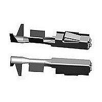
968137-5 TE Connectivity, 968137-5 Datasheet

968137-5
Specifications of 968137-5
Related parts for 968137-5
968137-5 Summary of contents
Page 1
Product Specification INHALTSVERZEICHNIS 1. ALLGEMEINES ................................................................................................................................ 1.1 Einleitung........................................................................................................................................... 1.2 Allgemeine Produktbeschreibung..................................................................................................... 1.3 Einsatzgebiet..................................................................................................................................... 1.4 Produktübersicht ............................................................................................................................... 2. ANZUWENDENDE UNTERLAGEN ................................................................................................ 2.1 AMP* Spezifikationen........................................................................................................................ 2.2 AMP* Zeichnungen ........................................................................................................................... 2.3 Normen.............................................................................................................................................. 3. BESCHREIBUNG DER KOMPONENTEN...................................................................................... 4. EIGENSCHAFTEN ........................................................................................................................... 4.1 Allgemeine Testbedingungen ........................................................................................................... ...
Page 2
Table of Contents 1. SCOPE ....................................................................................................................................... 1.1 Content ....................................................................................................................................... 1.2 General Product Description ...................................................................................................... 1.3 Application Sector....................................................................................................................... 1.4 Product List ................................................................................................................................ 2. APPLICABLE DOCUMENTS .................................................................................................... 2.1 AMP* Specifications ................................................................................................................... 2.2 AMP* Drawings .......................................................................................................................... 2.3 Other Standards ......................................................................................................................... 3. DESCRIPTION........................................................................................................................... 4. ...
Page 3
ALLGEMEINES 1.1 Einleitung Die vorliegende Spezifikation beschreibt den Aufbau, die Eigenschaften, Ausführungsarten, die Tests und die Qualitätsanforderungen des Micro Power Quadlok Systems (MPQ) + Power Quadlok Systems (PQ). 1.2 Allgemeine Produktbeschreibung Micro Power Quadlok und Power Quadlok ist die ...
Page 4
SCOPE 1.1 Content This specification describes the design, the characteristics, the versions, the tests and the quality requirements of the Micro Quadlok System (MQS). 1.2 General Product Description Micro Power Quadlok and Power Quadlok is the consequently further development ...
Page 5
ANZUWENDENDE UNTERLAGEN Soweit darauf Bezug genommen wird, bilden die folgenden Unterlagen einen Teil dieser Spezifikation. Wenn zwischen dieser Spezifikation und den genannten Unterlagen Unstimmigkeiten auftreten, hat diese Spezifikation Vorrang. Für die aufgeführten Unterlagen gilt jeweils der zum Zeitpunkt der ...
Page 6
APPLICABLE DOCUMENTS The following documents from a part of this specification to the extent specified herein. In the case of a conflict between this specification and the specified documents, this specification has priority. For the listed documents is valid ...
Page 7
EIGENSCHAFTEN 4.1 Allgemeine Testbedingungen Alle Tests, die an den einzelnen Teilen durchgeführt werden, müssen den angegebenen Prüfverfahren und Prüfrichtlinien entsprechen. - Anzahl der Prüflinge: min Für die mechanischen Tests sind die genannten Hilfswerkzeuge zu verwenden. - Die ...
Page 8
REQUIREMENTS 4.1 General Requirements All tests executed with the individual components must comply with the inspection plan in this specification. - Number of samples: at least 10 - The specified tools must be used for the mechanical tests. - ...
Page 9
Elektrische Kennwerte TESTBESCHREIBUNG Kontaktübergangswider- stände Crimpübergangs- widerstand Maximale Strombelastbarkeit für Crimpkontakt, "Frei in Luft" Strombelastbarkeit für "Kontakte im Gehäuse" (Derating) 4.3.1 Prüfaufbau für Stromerwärmung und Kontakübergangswiderstand Rev. B Eigenschaften R < Prüfbedingungen: K Leerlaufspannung < ...
Page 10
Electrical TEST DESCRIPTION Contact resistance Crimp resistance Maximum current carrying capacity for crimp contact, "in free air" Current carrying capacity "contacts in housing" (derating) 4.3.1 Test Equipment for Current Heating and Contact Resistance Rev. B Requirements R < 4 ...
Page 11
Mechanische Kennwerte BESCHREIBUNG MPQ Für den 1. Steckzyklus gilt:: Steckkräfte Steck- und Ziehkräfte 4,0N Ziehkräfte 2,0N Ausreißkraft der 1. Kontaktsicherung Kontakthaltekräfte in F Stahlnormkammer Ausreißkraft der 2. Kontaktsicherung F Haltekraft F Überfeder auf Kontaktkörper Rev. B Eigenschaften PQ Steckkräfte ...
Page 12
Mechanical TEST DESCRIPTION MPQ The following values apply to the first mating cycle: Mating force Mating and 4.0 N unmating forces Unmating force 2.0 N Contact retention Extraction force of first contact retention force in standard F steel cavity ...
Page 13
Verhalten unter Umweltbedingungen BESCHREIBUNG Der Durchgangswiderstand (Kontakt- + Crimpübergangs- widerstand) erhöht sich nach dem Elektrischer Streßtest gesamten Test gegenüber dem Ausgangswert um nicht mehr als 200%. Der Durchgangswiderstand der Kontakte erhöht sich nach Ablauf Salznebel mit der Prüfung gegenüber ...
Page 14
Environmentals TEST DESCRIPTION After the entire test, the total resistance (contact + crimp Electrical stress test resistance) increases by not more than 200% of the original value. After the entire test, the contact resistance increases by not more Salt ...
Page 15
Prüfablauf für verzinnte, vergoldete Oberflächen Test oder Prüfung Sichtprüfung Durchgangswiderstand nach DIN 41 640 T.4 Temperaturschock nach Dauer: 10 Zyklen / Temp.: -40 bis +100 C je 1h, verzinnt 20 Zyklen / Temp.: -40 bis +100 C je 1h, ...
Page 16
Procedure for Tin-Plated, Gold-Plated Contacts Test or Examination Visual inspection Contact resistance to IEC 512-2 DIN 41 640 P.4 Thermal shock to IEC 68 P.2-14 Na Duration: 10 cycles / temp.: -40 to +100° C per 1h, tin-plated 20 ...
Page 17
Strombelastbarkeit und Stromerwärmung (Derating-Kurven) 4.6 Current Carrying Capacity and Current Heating (Derating-Curves) 4.6.1 Einadrig frei in Luft, Oberfläche: verzinnt, vergoldet 4.6.1 Single-Wire in free air, Tin-Plated, Gold-Plated Abb. 1) Crimptechnik: 0,35 - 0,50mm² Fig. 1) Crimp connection: 0.35 - ...
Page 18
Abb. 1) Crimptechnik: 0,75 – 1,00mm² Fig. 1) Crimp connection: 0.75 – 1.00mm² Abb. 2) verzinnt ..................................................................... vergoldet Fig. 2) Tin-Plated ..............................................................Gold-Plated Derating - Kurve 1,0mm² 20 ...
Page 19
Abb. 1) Crimptechnik: 1,5 – 2,5mm² Fig. 1) Crimp connection: 1.5 – 2.5mm² Abb. 2) verzinnt ..................................................................... vergoldet Fig. 2) Tin-Plated ..............................................................Gold-Plated Derating - Kurve 2,5mm² 1,5mm² ...
Page 20
Abb. 1) Crimptechnik: 4,0mm² Fig. 1) Crimp connection: 4.0mm² Abb. 2) verzinnt Fig. 2) Tin-Plated Rev. ...
Page 21
Abb. 1) Crimptechnik: 1,5 – 4,0mm² Fig. 1) Crimp connection: 1.5 – 4.0mm² Abb. 2) verzinnt ..................................................................... vergoldet Fig. 2) Tin-Plated ..............................................................Gold-Plated Derating - Kurve 4,0mm² 40 2,5mm² ...
Page 22
Kupplung 22/8 pol. Stiftgehäuse-/30 pol. Buchsengehäuse PN 0-968 238/235-1 / 0-968 234-1, Oberfläche: verzinnt, MPQ-Buchsenkontakt / MPQ-Flachstecker 2,8x0,6 4.6.2 30-Pos. Coupling, 22/8 pos. pin housing, 30-pos. socket housing PN 0-968 238/235-1 / 0-968 234-1, Surface: Tin-Plated, MPQ socket ...
Page 23
Kupplung, 13 pol. Stiftwanne / 13 pol. Buchsengehäuse PN 0-967 441-1 / 0-968 112-1, Oberfläche: verzinnt 4.6.3 13-Pos. Coupling, 13 pos. pin tub / 13-pos. socket housing PN 0-967 441-1 / 0-968 112-1, Surface: Tin-Plated Abb. 1) Crimptechnik: ...
Page 24
Kupplung, 13 pol. Stiftwanne / 13 pol. Buchsengehäuse PN 0-967 441-1 / 0-968 112-1, Oberfläche: verzinnt 4.6.4 13-Pos. Coupling, 13 pos. pin tub / 13-pos. socket housing PN 0-967 441-1 / 0-968 112-1, Surface: Tin-Plated Abb. 1) Crimptechnik: ...
Page 25
Einadrig frei in Luft, Oberfläche: verzinnt 4.6.5 Single-wire in free air, Surface: Tin-Plated Abb. 1) Crimptechnik: 6,0 mm² - FLR Fig. 1) Crimp connection: 6.0 mm² FLR Abb. 2) verzinnt Fig. 2) Tin-Plated ...


