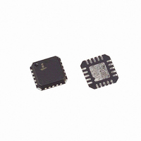
EL9115ILZ-T13 Intersil, EL9115ILZ-T13 Datasheet - Page 7

EL9115ILZ-T13
Manufacturer Part Number
EL9115ILZ-T13
Description
IC ANALOG DELAY LINE TRPL 20-QFN
Manufacturer
Intersil
Type
Video Delay Liner
Datasheet
1.EL9115ILZ-T13.pdf
(9 pages)
Specifications of EL9115ILZ-T13
Applications
Analog Beamforming, Skew Control
Mounting Type
Surface Mount
Package / Case
20-VQFN Exposed Pad, 20-HVQFN, 20-SQFN, 20-DHVQFN
Lead Free Status / RoHS Status
Lead free / RoHS Compliant
NOTE: Delay register word = 0abvwxyz; Red register - ab = 01;
Green register - ab = 10; Blue register - ab = 11; vwxyz selects delay.
TABLE 1. SERIAL BUS DATA (Continued)
vwxyz
01000
01001
01010
10000
10001
10010
10100
10101
00111
01011
01100
01101
01110
01111
10011
10110
10111
11000
11001
11010
11011
11100
11101
11110
11111
0
7
A1
a
DELAY
14
16
18
20
22
24
26
28
30
32
34
36
38
40
42
44
46
48
50
52
54
56
58
60
62
A0
b
D4
v
FIGURE 14.
EL9115
D3
w
Serial Bus Operation
On the first negative clock edge after NSEnable goes low,
read the input from DATA. This DATA level should be 0 (write
into registers); READ is not supported. Read the next two
data bits on subsequent negative edges and interpret them
as the register to be filled. Reg 01 = R, 02 = G, 03 = B, 00
test use. Read the next five bits of data and send them to
register. At the end of each block of 8 bits, any further data is
treated as being a new word. Data entered is shifted directly
to the final registers as it is clocked in. Initial value of all
registers on power-up is 0. It is the user's responsibility to
send complete patterns of 8 clock cycles, even if the first bit
is set to 1. If less than 8 bits are sent, data will only be
partially shifted through the registers. The pattern of 8 starts
with NSEnable going low, so it is good practice to frame
each word within an NS enable burst.
Test Pins
Three test pins are provided (Test R, Test G, Test B). During
normal operation, the test pins output pulses of current for a
duration of the overlap between the inputs, as shown in
Figure 15:
Test_R pulse = Red out (A) wrt Green out (B)
Test_G pulse = Green out
Test_B pulse = Blue out
Averaging the current gives a direct measure of the delay
between the two edges. When A precedes B the current
pulse is +50µA, and the output voltage goes up. When B
precedes A, the pulse is -50µA.
For the logic to work correctly, A and B must have a period of
overlap while they are high (a delay longer than the pulse
width cannot be measured).
D2
x
D1
y
D0
z
wrt Red out
wrt Blue out
NSENABLE
SCLOCK
SDATA
September 22, 2009
FN7441.5


