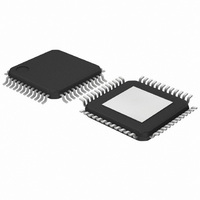
SAF7167AHW/V1,157 NXP Semiconductors, SAF7167AHW/V1,157 Datasheet - Page 7

SAF7167AHW/V1,157
Manufacturer Part Number
SAF7167AHW/V1,157
Description
IC DAC YUV TO RGB 48HTQFP
Manufacturer
NXP Semiconductors
Type
RGB Video Amplifierr
Datasheet
1.SAF7167AHWV1118.pdf
(21 pages)
Specifications of SAF7167AHW/V1,157
Applications
Video
Mounting Type
Surface Mount
Package / Case
48-TQFP Exposed Pad, 48-eTQFP, 48-HTQFP, 48-VQFP
Lead Free Status / RoHS Status
Lead free / RoHS Compliant
Other names
935269523157
SAF7167AHWBR
SAF7167AHWBR
SAF7167AHWBR
SAF7167AHWBR
Available stocks
Company
Part Number
Manufacturer
Quantity
Price
Company:
Part Number:
SAF7167AHW/V1,157
Manufacturer:
NXP Semiconductors
Quantity:
10 000
Philips Semiconductors
9397 750 12667
Product data sheet
7.1.2 YUV-to-RGB matrix
7.1.3 Triple 8-bit DACs
7.2 Analog mixers and keying control
Table 7:
For RGB 5 : 6 : 5 video inputs, the video data are just directly bypassed to triple DACs.
The input video data can be selected to either twos complement (I
binary offset (I
FMTC[1:0].
The rising edge of HREF input defines the start of active video data. When HREF is
inactive, the video output will be blanked.
The matrix converts YUV data, in accordance with ITU-R BT.601, to RGB data with
approximately 1.5 LSB deviation to the theoretical values for 8-bit resolution.
Three identical DACs for R, G and B video outputs are designed with voltage-drive
architecture to provide high-speed operation of up to 66 MHz conversion data rate. Pin
C_REF(H) is provided to allow for one external de-coupling capacitor to be connected
between the internal reference voltage source and ground.
The analog mixers are controlled to switch between the outputs from the video DACs and
analog RGB inputs by a keying signal. The analog RGB inputs need to interface with
analog mixers in the way of DC-coupling, also these RGB inputs are limited to RGB
signals without a sync level pedestal. The keying control can be enabled by setting
I
(from EXTKEY pin when KMOD[2:0] are all logic 0), and the other is the internal pixel
colour key (when KMOD[2:0] are not all logic 0) generated by comparing the input pixel
data with the internal I
are 4 ways to compare the pixel data (see
Input
UV0
YUV7
YUV6
YUV5
YUV4
YUV3
YUV2
YUV1
YUV0
RGB data
2
C-bus bit KEN = 1. Two kinds of keying are possible to generate: one is external key
Pixel byte sequence of 5 : 6 : 5
2
C-bus bit DRP = 1). The video input format is selected by I
Pixel byte sequence of RGB 5 : 6 : 5
G4
G3
G2
G1
B4
B3
B2
B1
B0
0
2
C-bus register value KD[7:0]. Controlled by KMOD[2:0] bits, there
Rev. 01 — 29 June 2004
G4
G3
G2
G1
B4
B3
B2
B1
B0
1
…continued
Table
YUV-to-RGB digital-to-analog converter
8).
G4
G3
G2
G1
B4
B3
B2
B1
B0
2
© Koninklijke Philips Electronics N.V. 2004. All rights reserved.
SAF7167AHW
2
C-bus bit DRP = 0) or
G4
G3
G2
G1
B4
B3
B2
B1
B0
3
2
C-bus bits
7 of 21


