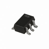
74AUP2G17GW,125 NXP Semiconductors, 74AUP2G17GW,125 Datasheet - Page 21

74AUP2G17GW,125
Manufacturer Part Number
74AUP2G17GW,125
Description
IC BUFF DL SCHM TRG L PWR SC88
Manufacturer
NXP Semiconductors
Series
74AUPr
Datasheet
1.74AUP2G17GM115.pdf
(21 pages)
Specifications of 74AUP2G17GW,125
Package / Case
SC-70-6, SC-88, SOT-363
Logic Type
Schmitt Trigger - Buffer, Driver
Number Of Elements
2
Number Of Bits Per Element
1
Current - Output High, Low
4mA, 4mA
Voltage - Supply
0.8 V ~ 3.6 V
Operating Temperature
-40°C ~ 125°C
Mounting Type
Surface Mount
Logic Family
AUP
Number Of Channels Per Chip
2
Polarity
Non-Inverting
Supply Voltage (max)
3.6 V
Supply Voltage (min)
0.8 V
Maximum Operating Temperature
+ 125 C
Mounting Style
SMD/SMT
High Level Output Current
- 4 mA
Input Bias Current (max)
0.5 uA
Low Level Output Current
4 mA
Minimum Operating Temperature
- 40 C
Propagation Delay Time
19 ns @ 1.1 V to 1.3 V or 11.2 ns @ 1.4 V to 1.6 V or 9.2 ns @ 1.65 V to 1.95 V or 7 ns @ 2.3 V to 2.7 V or 6.2 ns @ 3 V to 3.6 V
Number Of Lines (input / Output)
2 / 2
Lead Free Status / RoHS Status
Lead free / RoHS Compliant
Lead Free Status / RoHS Status
Lead free / RoHS Compliant, Lead free / RoHS Compliant
Other names
74AUP2G17GW-G
74AUP2G17GW-G
935279991125
74AUP2G17GW-G
935279991125
NXP Semiconductors
21. Contents
1
2
3
4
5
6
6.1
6.2
7
8
9
10
11
12
13
14
15
16
17
18
19
19.1
19.2
19.3
19.4
20
21
General description . . . . . . . . . . . . . . . . . . . . . . 1
Features and benefits . . . . . . . . . . . . . . . . . . . . 1
Ordering information . . . . . . . . . . . . . . . . . . . . . 2
Marking . . . . . . . . . . . . . . . . . . . . . . . . . . . . . . . . 2
Functional diagram . . . . . . . . . . . . . . . . . . . . . . 2
Pinning information . . . . . . . . . . . . . . . . . . . . . . 3
Functional description . . . . . . . . . . . . . . . . . . . 3
Limiting values. . . . . . . . . . . . . . . . . . . . . . . . . . 4
Recommended operating conditions. . . . . . . . 4
Static characteristics. . . . . . . . . . . . . . . . . . . . . 4
Dynamic characteristics . . . . . . . . . . . . . . . . . . 7
Waveforms . . . . . . . . . . . . . . . . . . . . . . . . . . . . . 8
Transfer characteristics . . . . . . . . . . . . . . . . . . 9
Waveforms transfer characteristics. . . . . . . . 10
Application information. . . . . . . . . . . . . . . . . . 12
Package outline . . . . . . . . . . . . . . . . . . . . . . . . 13
Abbreviations . . . . . . . . . . . . . . . . . . . . . . . . . . 18
Revision history . . . . . . . . . . . . . . . . . . . . . . . . 18
Legal information. . . . . . . . . . . . . . . . . . . . . . . 19
Contact information. . . . . . . . . . . . . . . . . . . . . 20
Contents . . . . . . . . . . . . . . . . . . . . . . . . . . . . . . 21
Pinning . . . . . . . . . . . . . . . . . . . . . . . . . . . . . . . 3
Pin description . . . . . . . . . . . . . . . . . . . . . . . . . 3
Data sheet status . . . . . . . . . . . . . . . . . . . . . . 19
Definitions . . . . . . . . . . . . . . . . . . . . . . . . . . . . 19
Disclaimers . . . . . . . . . . . . . . . . . . . . . . . . . . . 19
Trademarks. . . . . . . . . . . . . . . . . . . . . . . . . . . 20
Please be aware that important notices concerning this document and the product(s)
described herein, have been included in section ‘Legal information’.
© NXP B.V. 2010.
For more information, please visit: http://www.nxp.com
For sales office addresses, please send an email to: salesaddresses@nxp.com
Low-power dual Schmitt trigger
74AUP2G17
Date of release: 3 November 2010
Document identifier: 74AUP2G17
All rights reserved.


