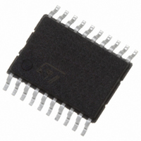
M74HCT574TTR STMicroelectronics, M74HCT574TTR Datasheet - Page 5

M74HCT574TTR
Manufacturer Part Number
M74HCT574TTR
Description
IC FLIP FLOP OCT D 3ST 20-TSSOP
Manufacturer
STMicroelectronics
Series
74HCTr
Type
D-Type Busr
Datasheet
1.M74HCT574B1R.pdf
(11 pages)
Specifications of M74HCT574TTR
Function
Standard
Output Type
Tri-State Non Inverted
Number Of Elements
1
Number Of Bits Per Element
8
Frequency - Clock
50MHz
Delay Time - Propagation
24ns
Trigger Type
Positive Edge
Current - Output High, Low
6mA, 6mA
Voltage - Supply
4.5 V ~ 5.5 V
Operating Temperature
-55°C ~ 125°C
Mounting Type
Surface Mount
Package / Case
20-TSSOP
Lead Free Status / RoHS Status
Lead free / RoHS Compliant
Other names
497-7401-2
M74HCT574TTR
M74HCT574TTR
AC ELECTRICAL CHARACTERISTICS (C
CAPACITIVE CHARACTERISTICS
1) C
load. (Refer to Test Circuit). Average operating current can be obtained by the following equation. I
Flip-Flop)
t
t
t
t
Symbol
Symbol
TLH
PLH
PZL
PLZ
C
t
t
f
C
PD
MAX
W(H)
W(H)
C
OUT
t
t
PD
s
h
IN
t
t
t
t
PZH
PHZ
is defined as the value of the IC’s internal equivalent capacitance which is calculated from the operating current consumption without
THL
PHL
Output Transition
Time
Propagation Delay
Time
High Impedance
Output Enable
Time
High Impedance
Output Disable
Time
Maximum Clock
Frequency
Minimum Pulse
Width (CK)
Minimum Set-up
Time
Minimum Hold
Time
Input Capacitance
Output
Capacitance
Power Dissipation
Capacitance (note
1)
Parameter
Parameter
V
V
(V)
4.5
4.5
4.5
4.5
4.5
4.5
4.5
4.5
(V)
CC
CC
Test Condition
Test Condition
(pF)
150
150
C
50
50
50
50
50
50
50
50
L
R
R
L
L
L
= 1 K
= 1 K
= 50 pF, Input t
Min.
Min.
31
T
T
A
A
r
Typ.
Typ.
= 25°C
= 25°C
20
24
19
23
19
50
10
63
= t
7
8
7
5
f
= 6ns)
Max.
Max.
12
30
36
30
36
30
15
15
10
0
Value
Value
-40 to 85°C
Min.
-40 to 85°C
Min.
CC(opr)
25
= C
Max.
Max.
15
38
45
38
45
38
19
19
10
0
PD
x V
-55 to 125°C
-55 to 125°C
Min.
Min.
CC
21
x f
M74HCT574
IN
Max.
Max.
+ I
18
45
54
45
54
45
22
22
10
0
CC
/8 (per
Unit
Unit
pF
pF
pF
ns
ns
ns
ns
ns
ns
ns
ns
5/11


