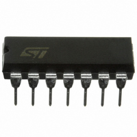
M74HC14B1R STMicroelectronics, M74HC14B1R Datasheet - Page 5

M74HC14B1R
Manufacturer Part Number
M74HC14B1R
Description
IC HEX INVERTER 14-DIP
Manufacturer
STMicroelectronics
Series
74HCr
Specifications of M74HC14B1R
Logic Type
Inverter with Schmitt Trigger
Number Of Inputs
1
Number Of Circuits
6
Current - Output High, Low
5.2mA, 5.2mA
Voltage - Supply
2 V ~ 6 V
Operating Temperature
-55°C ~ 125°C
Mounting Type
Through Hole
Package / Case
14-DIP (0.300", 7.62mm)
Logic Family
HCF40
High Level Output Current
- 5.2 mA
Low Level Output Current
5.2 mA
Propagation Delay Time
125 ns, 25 ns, 21 ns
Supply Voltage (max)
6 V
Supply Voltage (min)
2 V
Maximum Operating Temperature
+ 125 C
Minimum Operating Temperature
- 40 C
Mounting Style
Through Hole
Operating Supply Voltage
2 V to 6 V
Circuit Type
Silicon Gate
Current, Input, Diode
± 20 mA (Max.)
Current, Leakage, Input
±0.1 μA (Max.)
Current, Output, Dc
± 25 mA (Max.)
Current, Output, Diode
± 20 mA (Max.)
Current, Quiescent Supply
1 uA (Max.)
Current, Supply
20 μA
Logic Function
Inverter
Package Type
DIP-14
Power Dissipation
500 mW
Special Features
High Speed, Schmitt-Trigger
Temperature, Operating, Maximum
125 °C
Temperature, Operating, Minimum
-55 °C
Temperature, Operating, Range
-55 to +125 °C
Voltage, Dc Input
-0.5 to VCC + 0.5 V
Voltage, Dc Output
-0.5 to VCC + 0.5 V
Voltage, Supply
2 to 6 V
Lead Free Status / RoHS Status
Lead free / RoHS Compliant
Other names
497-1777-5
M74HC14
Table 7.
Table 8.
1. C
t
t
Symbol
Symbol
TLH
PLH
C
consumption without load. (Refer to test circuit). Average operating current can be obtained by the following equation:
I
C
CC(opr)
PD
PD
IN
t
t
THL
PHL
is defined as the value of the IC’s internal equivalent capacitance which is calculated from the operating current
= C
Output transition
time
Propagation delay
time
Input capacitance
Power dissipation
capacitance
PD
AC electrical characteristics (C
Capacitive characteristics
Parameter
Parameter
x V
CC
x f
(1)
IN
+ I
CC
/6(per gate).
V
V
(V)
5.0
5.0
(V)
2.0
4.5
6.0
2.0
4.5
6.0
CC
CC
Test condition
Test condition
f
IN
= 10 MHz
L
= 50 pF, Input t
Min
Min
T
T
A
A
= 25 °C
Typ
= 25°C
Typ
30
42
14
12
28
8
7
5
r
= t
f
Max
Max
= 6 ns)
125
75
15
13
25
21
10
Value
Value
-40 to 85 °C
-40 to 85°C
Min
Min
Electrical characteristics
Max
Max
155
95
19
16
31
16
10
Min
Min
125 °C
125°C
-55 to
-55 to
Max
Max
110
190
22
19
38
32
10
Unit
Unit
pF
pF
ns
ns
5/14


