74HC1GU04GW,125 NXP Semiconductors, 74HC1GU04GW,125 Datasheet
74HC1GU04GW,125
Specifications of 74HC1GU04GW,125
74HC1GU04GW-G
935261178125


Related parts for 74HC1GU04GW,125


74HC1GU04GW,125 Summary of contents
Page 1
Inverter Rev. 05 — 10 July 2007 1. General description The 74HC1GU04 is a high-speed Si-gate CMOS device. It provides an inverting single stage function. The standard output currents are half those of the 74HCU04. 2. Features I Symmetrical ...
Page 2
... NXP Semiconductors 6. Pinning information 6.1 Pinning Fig 4. Pin configuration 6.2 Pin description Table 3. Pin description Symbol Pin n. GND Functional description Table 4. Function table H = HIGH voltage level LOW voltage level Input 74HC1GU04_5 Product data sheet 74HC1GU04 n. GND Y 001aaf105 Description not connected ...
Page 3
... NXP Semiconductors 8. Limiting values Table 5. Limiting values In accordance with the Absolute Maximum Rating System (IEC 60134). Voltages are referenced to GND (ground = 0 V). Symbol Parameter V supply voltage CC I input clamping current IK I output clamping current OK I output current O I supply current CC I ground current ...
Page 4
... NXP Semiconductors Table 7. Static characteristics Voltages are referenced to GND (ground = 0 V). All typical values are measured at T Symbol Parameter V HIGH-level output OH voltage V LOW-level output OL voltage I input leakage current I I supply current CC C input capacitance I 11. Dynamic characteristics Table 8. Dynamic characteristics GND = 6.0 ns ...
Page 5
... NXP Semiconductors 12. Waveforms ( input M t PHL (1) Y output GND Fig 5. Input to output propagation delays 13. Typical transfer characteristics (mA) 0 Fig 2 74HC1GU04_5 Product data sheet t PLH GENERATOR mna046 . Test data is given in CC DUT = Device Under Test C capacitance. R output impedance Z Fig 6. Load circuitry for switching times ...
Page 6
... NXP Semiconductors (mA Fig 6 14. Application information Some applications are: • Linear amplifier (see • In crystal oscillator design (see Remark: All values given are typical unless otherwise specifi U04 Maximum 1.5 V centered at o(p- – --------------------------------------- ------ - open loop gain voltage gain ...
Page 7
... NXP Semiconductors Table 9. External components for resonator (f < 1 MHz) All values given are typical and must be used as an initial set-up Frequency 10 kHz to 15.9 kHz 16 kHz to 24.9 kHz 25 kHz to 54.9 kHz 55 kHz to 129.9 kHz 130 kHz to 199.9 kHz 200 kHz to 349.9 kHz 350 kHz to 600 kHz Table 10 ...
Page 8
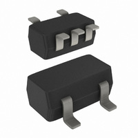
... NXP Semiconductors 15. Package outline TSSOP5: plastic thin shrink small outline package; 5 leads; body width 1. DIMENSIONS (mm are the original dimensions UNIT max. 0.1 1.0 mm 1.1 0.15 0 0.8 Note 1. Plastic or metal protrusions of 0.15 mm maximum per side are not included. OUTLINE VERSION IEC SOT353-1 Fig 14 ...
Page 9
... NXP Semiconductors Plastic surface-mounted package; 5 leads DIMENSIONS (mm are the original dimensions UNIT 0.100 0.40 1.1 0.26 mm 0.013 0.25 0.9 0.10 OUTLINE VERSION IEC SOT753 Fig 15. Package outline SOT753 (SC-74A) 74HC1GU04_5 Product data sheet scale 3.1 1.7 3.0 0.6 0.95 2.7 1.3 2 ...
Page 10
... Release date 74HC1GU04_5 20070710 • Modifications: The format of this data sheet has been redesigned to comply with the new identity guidelines of NXP Semiconductors. • Legal texts have been adapted to the new company name where appropriate. • Package SOT353 changed to SOT353-1 in • ...
Page 11
... For detailed and full information see the relevant full data sheet, which is available on request via the local NXP Semiconductors sales office. In case of any inconsistency or conflict with the short data sheet, the full data sheet shall prevail ...
Page 12
... NXP Semiconductors 19. Contents 1 General description . . . . . . . . . . . . . . . . . . . . . . 1 2 Features . . . . . . . . . . . . . . . . . . . . . . . . . . . . . . . 1 3 Ordering information . . . . . . . . . . . . . . . . . . . . . 1 4 Marking . . . . . . . . . . . . . . . . . . . . . . . . . . . . . . . . 1 5 Functional diagram . . . . . . . . . . . . . . . . . . . . . . 1 6 Pinning information . . . . . . . . . . . . . . . . . . . . . . 2 6.1 Pinning . . . . . . . . . . . . . . . . . . . . . . . . . . . . . . . 2 6.2 Pin description . . . . . . . . . . . . . . . . . . . . . . . . . 2 7 Functional description . . . . . . . . . . . . . . . . . . . 2 8 Limiting values Recommended operating conditions Static characteristics Dynamic characteristics . . . . . . . . . . . . . . . . . . 4 12 Waveforms . . . . . . . . . . . . . . . . . . . . . . . . . . . . . 5 13 Typical transfer characteristics . . . . . . . . . . . . 5 14 Application information ...