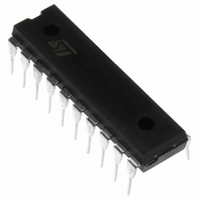
M74HC573B1R STMicroelectronics, M74HC573B1R Datasheet - Page 6

M74HC573B1R
Manufacturer Part Number
M74HC573B1R
Description
IC LATCH OCTAL D-TYPE 20-DIP
Manufacturer
STMicroelectronics
Series
74HCr
Specifications of M74HC573B1R
Logic Type
D-Type Transparent Latch
Circuit
8:8
Output Type
Tri-State
Voltage - Supply
2 V ~ 6 V
Independent Circuits
1
Delay Time - Propagation
12ns
Current - Output High, Low
7.8mA, 7.8mA
Operating Temperature
-55°C ~ 125°C
Mounting Type
Through Hole
Package / Case
20-DIP (0.300", 7.62mm)
Number Of Circuits
8
Logic Family
74HC
Polarity
Non-Inverting
Input Bias Current (max)
4 uA
High Level Output Current
- 7.8 mA
Low Level Output Current
32 mA
Propagation Delay Time
150 ns at 2 V, 30 ns at 4.5 V, 26 ns at 6 V
Supply Voltage (max)
6 V
Supply Voltage (min)
2 V
Maximum Operating Temperature
+ 125 C
Minimum Operating Temperature
- 55 C
Mounting Style
Through Hole
Circuit Type
Silicon Gate
Current, Leakage, Input
±0.1 μA (Max.)
Current, Quiescent Supply
4 uA (Max.)
Current, Supply
80 μA
Function Type
8-Bits, D-Type
Input Fall Time
0 to 1000 ns @ 2V, 0 to 500 ns @ 4.5 V, 0 to 400 ns @ 6 V
Input Rise Time
0 to 1000 ns @ 2V, 0 to 500 ns @ 4.5 V, 0 to 400 ns @ 6 V
Logic Function
Latch
Package Type
DIP-20
Power Dissipation
500 mW
Special Features
High Speed, Tri-State
Temperature, Operating, Maximum
125 °C
Temperature, Operating, Minimum
-55 °C
Temperature, Operating, Range
-55 to +125 °C
Voltage, Dc Input
-0.5 to +0.5
Voltage, Dc Output
-0.5 to +0.5
Voltage, Supply
2 to 6 V
Lead Free Status / RoHS Status
Lead free / RoHS Compliant
Other names
497-1875-5
Available stocks
Company
Part Number
Manufacturer
Quantity
Price
M74HC573
6/12
CAPACITIVE CHARACTERISTICS
1) C
load. (Refer to Test Circuit). Average operating current can be obtained by the following equation. I
Flop) and the C
TEST CIRCUIT
C
R
R
t
t
t
PLH
PZL
PZH
L
1
T
Symbol
= 50pF/150pF or equivalent (includes jig and probe capacitance)
= 1K
C
= Z
C
PD
C
OUT
, t
, t
, t
PD
IN
OUT
is defined as the value of the IC’s internal equivalent capacitance which is calculated from the operating current consumption without
PLZ
PHL
PHZ
or equivalent
of pulse generator (typically 50 )
Input Capacitance
Output
Capacitance
Power Dissipation
Capacitance (note
1)
PD
Parameter
when n pcs of Flip Flop operate, can be gained by the following equation: C
V
(V)
CC
Test Condition
TEST
Min.
T
A
Typ.
= 25°C
10
51
5
Max.
10
PD(TOTAL)
Value
Min.
CC(opr)
-40 to 85°C
= 33 + 18 x n (pF)
= C
Max.
10
PD
x V
SWITCH
-55 to 125°C
CC
Min.
Open
GND
V
x f
CC
IN
+ I
Max.
10
CC
/8 (per Flip
Unit
pF
pF
pF


