CBT3251DB,118 NXP Semiconductors, CBT3251DB,118 Datasheet - Page 14
CBT3251DB,118
Manufacturer Part Number
CBT3251DB,118
Description
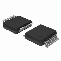
IC 1-OF-8 FET MUX/DEMUX 16-SSOP
Manufacturer
NXP Semiconductors
Series
74CBTr
Type
FET Multiplexer/Demuxr
Datasheet
1.CBT3251DB112.pdf
(16 pages)
Specifications of CBT3251DB,118
Circuit
1 x 1:8
Independent Circuits
1
Current - Output High, Low
15mA, 64mA
Voltage Supply Source
Single Supply
Voltage - Supply
4.5 V ~ 5.5 V
Operating Temperature
-40°C ~ 85°C
Mounting Type
Surface Mount
Package / Case
16-SSOP
Logic Family
CBT
Number Of Bits
8
Number Of Elements
1
Technology
CMOS
On Resistance
14Ohm
Propagation Delay Time
6.4ns
Package Type
SSOP
Operating Temp Range
-40C to 85C
Operating Temperature Classification
Industrial
Operating Supply Voltage (min)
4.5V
Operating Supply Voltage (typ)
5V
Operating Supply Voltage (max)
5.5V
Quiescent Current
3uA
Pin Count
16
Mounting
Surface Mount
Lead Free Status / RoHS Status
Lead free / RoHS Compliant
Other names
935274114118
CBT3251DB-T
CBT3251DB-T
CBT3251DB-T
CBT3251DB-T


Philips Semiconductors
14. Abbreviations
15. Revision history
Table 11:
CBT3251_1
Product data sheet
Document ID
CBT3251_1
Revision history
Release date
20051221
[4]
[5]
[6]
[7]
[8]
[9]
Table 10:
Acronym
CDM
ESD
FET
HBM
MM
PRR
TTL
These packages are not suitable for wave soldering. On versions with the heatsink on the bottom side, the
solder cannot penetrate between the printed-circuit board and the heatsink. On versions with the heatsink
on the top side, the solder might be deposited on the heatsink surface.
If wave soldering is considered, then the package must be placed at a 45 angle to the solder wave
direction. The package footprint must incorporate solder thieves downstream and at the side corners.
Wave soldering is suitable for LQFP, QFP and TQFP packages with a pitch (e) larger than 0.8 mm; it is
definitely not suitable for packages with a pitch (e) equal to or smaller than 0.65 mm.
Wave soldering is suitable for SSOP, TSSOP, VSO and VSSOP packages with a pitch (e) equal to or larger
than 0.65 mm; it is definitely not suitable for packages with a pitch (e) equal to or smaller than 0.5 mm.
Image sensor packages in principle should not be soldered. They are mounted in sockets or delivered
pre-mounted on flex foil. However, the image sensor package can be mounted by the client on a flex foil by
using a hot bar soldering process. The appropriate soldering profile can be provided on request.
Hot bar soldering or manual soldering is suitable for PMFP packages.
Abbreviations
Data sheet status
Product data sheet
Description
Charged Device Model
ElectroStatic Discharge
Field-Effect Transistor
Human Body Model
Machine Model
Pulse Repetition Rate
Transistor-Transistor Logic
Rev. 01 — 21 December 2005
Change notice
-
1-of-8 FET multiplexer/demultiplexer
Doc. number
-
© Koninklijke Philips Electronics N.V. 2005. All rights reserved.
Supersedes
-
CBT3251
14 of 16
Related parts for CBT3251DB,118
Image
Part Number
Description
Manufacturer
Datasheet
Request
R

Part Number:
Description:
IC 1BIT 1:8 FET MUX/DEMUX 16SOIC
Manufacturer:
NXP Semiconductors
Datasheet:
Part Number:
Description:
IC 1-OF-8 FET MUX/DEMUX 16-SOIC
Manufacturer:
NXP Semiconductors
Datasheet:

Part Number:
Description:
Encoders, Decoders, Multiplexers & Demultiplexers 1OF8 FET MULTIPLXR/ DEMUX
Manufacturer:
NXP Semiconductors
Part Number:
Description:
Encoders, Decoders, Multiplexers & Demultiplexers 1OF8 FET MULTIPLXR/ DEMUX
Manufacturer:
NXP Semiconductors

Part Number:
Description:
CBT3251 1-of-8 FET multiplexer/demultiplexer
Manufacturer:
PHILIPS [NXP Semiconductors]
Datasheet:
Part Number:
Description:
Cbt3251 1-of-8 Fet Multiplexer/demultiplexer
Manufacturer:
NXP Semiconductors
Datasheet:
Part Number:
Description:
NXP Semiconductors designed the LPC2420/2460 microcontroller around a 16-bit/32-bitARM7TDMI-S CPU core with real-time debug interfaces that include both JTAG andembedded trace
Manufacturer:
NXP Semiconductors
Datasheet:

Part Number:
Description:
NXP Semiconductors designed the LPC2458 microcontroller around a 16-bit/32-bitARM7TDMI-S CPU core with real-time debug interfaces that include both JTAG andembedded trace
Manufacturer:
NXP Semiconductors
Datasheet:
Part Number:
Description:
NXP Semiconductors designed the LPC2468 microcontroller around a 16-bit/32-bitARM7TDMI-S CPU core with real-time debug interfaces that include both JTAG andembedded trace
Manufacturer:
NXP Semiconductors
Datasheet:
Part Number:
Description:
NXP Semiconductors designed the LPC2470 microcontroller, powered by theARM7TDMI-S core, to be a highly integrated microcontroller for a wide range ofapplications that require advanced communications and high quality graphic displays
Manufacturer:
NXP Semiconductors
Datasheet:
Part Number:
Description:
NXP Semiconductors designed the LPC2478 microcontroller, powered by theARM7TDMI-S core, to be a highly integrated microcontroller for a wide range ofapplications that require advanced communications and high quality graphic displays
Manufacturer:
NXP Semiconductors
Datasheet:
Part Number:
Description:
The Philips Semiconductors XA (eXtended Architecture) family of 16-bit single-chip microcontrollers is powerful enough to easily handle the requirements of high performance embedded applications, yet inexpensive enough to compete in the market for hi
Manufacturer:
NXP Semiconductors
Datasheet:
Part Number:
Description:
The XA-S3 device is a member of Philips Semiconductors? XA(eXtended Architecture) family of high performance 16-bitsingle-chip microcontrollers
Manufacturer:
NXP Semiconductors
Datasheet:

Part Number:
Description:
The NXP BlueStreak LH75401/LH75411 family consists of two low-cost 16/32-bit System-on-Chip (SoC) devices
Manufacturer:
NXP Semiconductors
Datasheet: