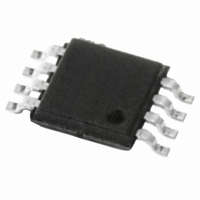
M95128-RDW6TP STMicroelectronics, M95128-RDW6TP Datasheet - Page 27

M95128-RDW6TP
Manufacturer Part Number
M95128-RDW6TP
Description
IC EEPROM 128KBIT 2MHZ 8TSSOP
Manufacturer
STMicroelectronics
Datasheet
1.M95128-RMN6TP.pdf
(44 pages)
Specifications of M95128-RDW6TP
Format - Memory
EEPROMs - Serial
Memory Type
EEPROM
Memory Size
128K (16K x 8)
Speed
2MHz
Interface
SPI, 3-Wire Serial
Voltage - Supply
1.8 V ~ 5.5 V
Operating Temperature
-40°C ~ 85°C
Package / Case
8-TSSOP
Density
128Kb
Interface Type
Serial (SPI)
Organization
16Kx8
Access Time (max)
150ns
Frequency (max)
2MHz
Write Protection
Yes
Data Retention
40Year
Operating Supply Voltage (typ)
2.5/3.3/5V
Package Type
TSSOP
Operating Temp Range
-40C to 85C
Supply Current
3mA
Operating Supply Voltage (min)
1.8V
Operating Supply Voltage (max)
5.5V
Operating Temperature Classification
Industrial
Mounting
Surface Mount
Pin Count
8
Maximum Clock Frequency
2 MHz
Access Time
150 ns
Supply Voltage (max)
5.5 V
Supply Voltage (min)
1.8 V
Maximum Operating Current
3 mA
Maximum Operating Temperature
+ 85 C
Mounting Style
SMD/SMT
Minimum Operating Temperature
- 40 C
Operating Supply Voltage
2.5 V, 3.3 V, 5 V
Lead Free Status / RoHS Status
Lead free / RoHS Compliant
Other names
497-8684-2
M95128-RDW6TP
M95128-RDW6TP
Available stocks
Company
Part Number
Manufacturer
Quantity
Price
Company:
Part Number:
M95128-RDW6TP
Manufacturer:
STMicroelectronics
Quantity:
495
Part Number:
M95128-RDW6TP
Manufacturer:
ST
Quantity:
20 000
M95128, M95128-W, M95128-R
Table 10.
1. Output Hi-Z is defined as the point where data out is no longer driven.
Figure 14. AC measurement I/O waveform
Table 11.
1. Sampled only, not 100% tested, at T
Table 12.
1. For all 5V range devices, the device meets the output requirements for both TTL and CMOS standards.
C
C
Symbol
Symbol
V
OUT
IN
V
Symbol
V
I
RES
OH
I
V
OL
I
CC1
V
I
CC
LO
LI
C
IH
IL
(1)
(1)
L
(2)
Input leakage current
Output leakage current
Supply current
Supply current
(Standby Power mode)
Input low voltage
Input high voltage
Output low voltage
Output high voltage
Internal reset threshold
voltage
Output capacitance (Q)
Input capacitance (D)
Input capacitance (other pins)
Load capacitance
Input rise and fall times
Input pulse voltages
Input and output
AC measurement conditions
Capacitance
DC characteristics (M95128, device grade 3)
Parameter
Parameter
0.8V CC
0.2V CC
Input Levels
(1)
(1)
Parameter
timing reference voltages
Doc ID 5798 Rev 13
A
=25 °C and a frequency of 5 MHz.
C = 0.1V
C = 0.1V
S = V
I
OH
I
OL
V
V
S = V
CC
CC
V
CC
V
= –2 mA, V
Test condition
= 2 mA, V
Test condition
IN
IN
CC
, V
CC
= 5 V, Q = open
= 5 V, Q = open
V
= V
= V
CC
V
V
/0.9V
OUT
OUT
/0.9V
IN
IN
, V
SS
SS
Timing Reference Levels
= 0 V
= 0 V
= 0 V
= V
CC
CC
or V
or V
CC
CC
CC
= 5 V,
SS
at 10 MHz,
at 5 MHz,
Input and Output
= 5 V
CC
CC
= 5 V
or V
Min.
0.2V
0.3V
100
CC
AI00825B
0.7V CC
0.3V CC
CC
CC
Min.
0.7 V
0.8 V
to 0.8V
to 0.7V
DC and AC parameters
–0.45
Min.
2.5
Max.
CC
CC
8
8
6
50
CC
CC
Max.
0.3 V
V
Max.
CC
± 2
± 2
0.4
4.0
4
8
5
+1
CC
pF
pF
pF
Unit
pF
ns
Unit
V
V
Unit
mA
mA
27/44
µA
µA
µA
V
V
V
V
V


