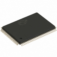
CY7C1338G-117AXC Cypress Semiconductor Corp, CY7C1338G-117AXC Datasheet - Page 5

CY7C1338G-117AXC
Manufacturer Part Number
CY7C1338G-117AXC
Description
IC SRAM 4MBIT 117MHZ 100LQFP
Manufacturer
Cypress Semiconductor Corp
Datasheet
1.CY7C1338G-117AXC.pdf
(17 pages)
Specifications of CY7C1338G-117AXC
Format - Memory
RAM
Memory Type
SRAM - Synchronous
Memory Size
4M (128K x 32)
Speed
117MHz
Interface
Parallel
Voltage - Supply
3.15 V ~ 3.6 V
Operating Temperature
0°C ~ 70°C
Package / Case
100-LQFP
Lead Free Status / RoHS Status
Lead free / RoHS Compliant
Available stocks
Company
Part Number
Manufacturer
Quantity
Price
Company:
Part Number:
CY7C1338G-117AXC
Manufacturer:
Cypress Semiconductor Corp
Quantity:
10 000
Document #: 38-05521 Rev. *A
Single Write Accesses Initiated by ADSC
This write access is initiated when the following conditions are
satisfied at clock rise: (1) CE
active, (2) ADSC is asserted LOW, (3) ADSP is deasserted
HIGH, and (4) the write input signals (GW, BWE, and BW
indicate a write access. ADSC is ignored if ADSP is active
LOW.
The addresses presented are loaded into the address register
and the burst counter/control logic and delivered to the
memory core. The information presented to DQ
written into the specified address location. Byte writes are
allowed. During byte writes, BW
DQ
tri-stated when a write is detected, even a byte write. Since this
is a common I/O device, the asynchronous OE input signal
must be deasserted and the I/Os must be tri-stated prior to the
presentation of data to DQs. As a safety precaution, the data
lines are tri-stated once a write cycle is detected, regardless
of the state of OE.
Burst Sequences
The CY7C1338G provides an on-chip two-bit wraparound
burst counter inside the SRAM. The burst counter is fed by
A[1:0], and can follow either a linear or interleaved burst order.
The burst order is determined by the state of the MODE input.
A LOW on MODE will select a linear burst sequence. A HIGH
on MODE will select an interleaved burst order. Leaving
MODE unconnected will cause the device to default to a inter-
leaved burst sequence.
ZZ Mode Electrical Characteristics
I
t
t
t
t
DDZZ
ZZS
ZZREC
ZZI
RZZI
B
Parameter
, BW
C
controls DQ
Snooze mode standby current
Device operation to ZZ
ZZ recovery time
ZZ active to snooze current
ZZ Inactive to exit snooze current
C
, and BW
1
, CE
A
controls DQ
D
Description
2
, and CE
controls DQ
3
A
are all asserted
, BW
D
. All I/Os are
[A:D]
PRELIMINARY
B
controls
will be
[A:D]
)
ZZ > V
ZZ > V
ZZ < 0.2V
This parameter is sampled
This parameter is sampled
Sleep Mode
The ZZ input pin is an asynchronous input. Asserting ZZ
places the SRAM in a power conservation “sleep” mode. Two
clock cycles are required to enter into or exit from this “sleep”
mode. While in this mode, data integrity is guaranteed.
Accesses pending when entering the “sleep” mode are not
considered valid nor is the completion of the operation
guaranteed. The device must be deselected prior to entering
the “sleep” mode. CEs, ADSP, and ADSC must remain
inactive for the duration of t
LOW.
Interleaved Burst Address Table
(MODE = Floating or V
Linear Burst Address Table (MODE = GND)
Address
Address
Test Conditions
A1, A0
DD
DD
A
First
First
1
00
01
10
11
00
01
10
11
, A
– 0.2V
– 0.2V
0
Address
Address
Second
Second
A1, A0
A
1
01
10
00
01
00
11
10
11
, A
0
ZZREC
DD
2t
Min.
CYC
0
)
Address
Address
A1, A0
A
after the ZZ input returns
Third
Third
1
10
00
01
10
11
00
01
11
, A
CY7C1338G
0
2t
2t
Max.
40
CYC
CYC
Page 5 of 17
Address
Address
Fourth
Fourth
A1, A0
A
1
00
01
10
11
10
01
00
11
, A
Unit
mA
ns
ns
ns
ns
0


