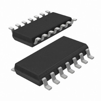
TEA1520T/N2,518 NXP Semiconductors, TEA1520T/N2,518 Datasheet - Page 5

TEA1520T/N2,518
Manufacturer Part Number
TEA1520T/N2,518
Description
IC CTRLR SMPS OVP OTP HV 14SOIC
Manufacturer
NXP Semiconductors
Series
STARplug™r
Specifications of TEA1520T/N2,518
Output Isolation
Isolated
Frequency Range
10 ~ 200kHz
Voltage - Input
7.5 ~ 40 V
Voltage - Output
650V
Power (watts)
1W
Operating Temperature
-40°C ~ 145°C
Package / Case
14-SOIC (0.154", 3.90mm Width)
Output Voltage
650 V
Output Current
125 uA
Mounting Style
SMD/SMT
For Use With
568-4326 - KIT DEMO STARPLUG BRONCO II
Lead Free Status / RoHS Status
Lead free / RoHS Compliant
Other names
568-2333-2
935269963518
TEA1520TD-T
935269963518
TEA1520TD-T
Philips Semiconductors
8. Functional description
TEA152X_FAM_2
Product data sheet
8.1 Start-up and undervoltage lock-out
8.2 Oscillator
8.3 Duty factor control
The TEA152x family is the heart of a compact flyback converter, with the IC placed at the
primary side. The auxiliary winding of the transformer can be used for indirect feedback to
control the isolated output. This additional winding also powers the IC. A more accurate
control of the output voltage and/or current can be implemented with an additional
secondary sensing circuit and optocoupler feedback.
The TEA152x family uses voltage mode control. The frequency is determined by the
maximum transformer demagnetizing time and the time of the oscillator. In the first case,
the converter operates in the Self Oscillating Power Supply (SOPS) mode. In the latter
case, it operates at a constant frequency, which can be adjusted with external
components R
Furthermore, a primary stroke is started only in a valley of the secondary ringing. This
valley switching principle minimizes capacitive switch-on losses.
Initially, the IC is self supplying from the rectified mains voltage. The IC starts switching as
soon as the voltage on pin V
auxiliary winding of the transformer as soon as V
the line is stopped for high efficiency operation.
When for some reason the auxiliary supply is not sufficient, the high-voltage supply also
supplies the IC. As soon as the voltage on pin V
stops switching and restarts from the rectified mains voltage.
The frequency of the oscillator is set by the external resistor and capacitor on pin RC. The
external capacitor is charged rapidly to the V
stroke, it discharges to the V
relative sensitivity of the duty factor to the regulation voltage at low duty factor is almost
equal to the sensitivity at high duty factors. This results in a more constant gain over the
duty factor range compared to PWM systems with a linear sawtooth oscillator. Stable
operation at low duty factors is easily realized. For high efficiency, the frequency is
reduced as soon as the duty factor drops below a certain value. This is accomplished by
increasing the oscillator charge time.
To ensure that the capacitor can be charged within the charge time, the value of the
oscillator capacitor should be limited to approximately 1 nF.
The duty factor is controlled by the internal regulation voltage and the oscillator signal on
pin RC. The internal regulation voltage is equal to the external regulation voltage (minus
2.5 V) multiplied by the gain of the error amplifier (typically 20 dB which is 10 ).
RC
and C
Rev. 02 — 25 January 2006
RC
. This mode is called Pulse Width Modulation (PWM).
CC
RC(min)
passes the V
level. Because the discharge is exponential, the
RC(max)
CC(start)
CC
CC
drops below the V
level and, starting from a new primary
is high enough and the supply from
level. The supply is taken over by the
SMPS ICs for low-power systems
TEA152x family
© Koninklijke Philips Electronics N.V. 2006. All rights reserved.
CC(stop)
level, the IC
5 of 20


