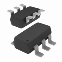
NCP1215ASNT1G ON Semiconductor, NCP1215ASNT1G Datasheet - Page 11

NCP1215ASNT1G
Manufacturer Part Number
NCP1215ASNT1G
Description
IC CTRLR CM UVLO 6TSOP
Manufacturer
ON Semiconductor
Datasheet
1.NCP1215ASNT1.pdf
(15 pages)
Specifications of NCP1215ASNT1G
Output Isolation
Isolated
Voltage - Input
8 ~ 18 V
Operating Temperature
25°C ~ 150°C
Package / Case
SC-74, SOT-457
Mounting Style
SMD/SMT
Lead Free Status / RoHS Status
Lead free / RoHS Compliant
Other names
NCP1215ASNT1G
NCP1215ASNT1GOSTR
NCP1215ASNT1GOSTR
cross- -section area A
allows to use
B
of the secondary winding can be calculated accounting
Schottky diode for output rectifier as follows:
calculated similarly:
calculations. The current sense method allows choosing the
voltage drop across the current sense resistor. Let’s use a
value of 0.5 V. The value of the current sense resistor can
then be evaluated as follows:
max
The EF16 core for transformer was selected. It has
The number of turns of the primary winding is:
The A
For an adapter output voltage of 6.5 V, the number of turns
The number of turns for auxiliary winding can be
The peak primary current is known from initial
R CS =
n s =
= 0.28 Tesla.
n s =
=
L
=
n p =
factor of the transformer’s core can be calculated:
A L =
(V s + V fwd )(1 − δ max )n p
(12 + 1)(1 − 0.5)150
(V s + V fwd )(1 − δ max )n p
(6.5 + 0.7)(1 − 0.5)150
V CS
I ppk
=
δ max · V bulk-- min
δ max · V bulk-- min
4.14 · 10 --3 · 0.2047
B max · A e
(n p ) 2
L p · I ppk
0.28 · 20.1 · 10 --6
0.5 · 127
L p
=
0.5 · 127
maximum operating
0.2047
e
=
0.5
= 20.1 mm
4.14 · 10 --3 ·
(150) 2
= 2.442 Ω = 2.7 Ω
= 15.35 = 15 turns
2
= 8.5 = 9 turns
= 150 turns
. The N67 magnetic
= 184 nH
flux density
(eq. 20)
(eq. 21)
(eq. 22)
(eq. 23)
(eq. 24)
http://onsemi.com
11
recalculated:
to be calculated for minimum bulk capacitor voltage since
at these conditions the converter should be able to deliver
specified maximum output power. The value of the timing
capacitor is then given by the following equation:
and V
schematic depicted in Figure 21.
The voltage drop across the sense resistor needs to be
Using the above results the value of the shift resistor is:
The value of timing capacitor for the off time control has
The value of the startup resistor for startup time of 200 ms
The result of all the calculations is the application
V CS = R CS · I ppk = 2.7 · 0.2047 = 0.553 V
C T =
R shift =
CC
R startup =
=
capacitor of 200 nF is following:
f sw
75 · 10 3
1
1.2 · 10 6
1
−
V CS
I CS
V bulk-- min
=
= 5.77 MΩ = 5.6 MΩ
−
Lp · I ppk
0.12 · 10 6
=
200 · 10 --9
4.14 · 10 −3 · 0.2047
C Vcc
50 · 10 --6
0.553
127
V startup
t startup
V bulk-- min
127
0.2
12
= 11.06 kΩ = 11 kΩ
+ I CC--start MAX
+ 10 · 10 --6
= 55.5 pF = 56 pF
(eq. 25)
(eq. 26)
(eq. 27)
(eq. 28)


