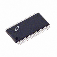
LTC1760CFW#PBF Linear Technology, LTC1760CFW#PBF Datasheet - Page 31

LTC1760CFW#PBF
Manufacturer Part Number
LTC1760CFW#PBF
Description
IC MANAGER BATTERY DUAL 48TSSOP
Manufacturer
Linear Technology
Datasheet
1.LTC1760CFWPBF.pdf
(44 pages)
Specifications of LTC1760CFW#PBF
Function
Charge Management
Battery Type
Smart Batteries
Voltage - Supply
6 V ~ 28 V
Operating Temperature
0°C ~ 70°C
Mounting Type
Surface Mount
Package / Case
48-TFSOP (0.240", 6.10mm Width)
Lead Free Status / RoHS Status
Lead free / RoHS Compliant
Available stocks
Company
Part Number
Manufacturer
Quantity
Price
OPERATIO
8 PowerPath Controller
The PowerPath switches are turned on and off by the
power management algorithm. The external PFETs are
usually connected as an input switch and an output switch.
The output switch PFET is connected in series with the
input PFET and the positive side of the short-circuit
sensing resistor, R
series between the power source and the output PFET. The
PowerPath switch driver equivalent circuit is shown in
Figure 6. The output PFET is driven ON or OFF by the output
side driver controlling pin GB10. The gate of the input PFET
is driven by an error amplifier which monitors the voltage
between the input power source (BAT1 in this case) and
SCP. If the switch is turned off, the two outputs are driven
to the higher of the two voltages present across the
input/SCP terminals of the switch. When the switch is
instructed to turn on, the output side driver immediately
drives the gate of the output PFET approximately 6V below
the highest of the voltages present at the input/SCP. When
the output PFET turns on, the voltage at SCP will be pulled
up to a diode drop below the source voltage by the bulk
diode of the input PFET. If the source voltage is more than
25mV above SCP, EAP will drive the gate of the input PFET
low until the input PFET turns on and reduces the voltage
across the input/SCP to the EAP set point, or until the
Zener clamp engages to limit the voltage applied to the
input PFET. If the source voltage drops more than 20mV
below SCP, then comparator CP turns on SWP to quickly
prevent large reverse current in the switch. This operation
mimics a diode with a low forward voltage drop.
BATTERY
FROM
1
BAT1
SCP
Figure 6. PowerPath Driver Equivalent Circuit
20mV
25mV
–
+
–
+
U
CP
EAP
SC
. The input switch is connected in
OFF
OFF
SWP
GB1I
GB1O
C
L
R
SC
Q7
Q8
TO LOAD
1760 F06
8.1 Autonomous PowerPath Switching
The LOPWR comparator monitors the voltage at the load
through the resistor divider from pin SCN. If LTC
(POWER_OFF) is low and the LOPWR comparator trips,
then all of the switches are turned on (3-Diode mode) by
the Autonomous PowerPath Controller to ensure that the
system is powered from the source with the highest volt-
age. The Autonomous PowerPath Controller waits approxi-
mately 1second, to allow power to stabilize, and then re-
verts back to the PowerPath switch configuration requested
by the PowerPath Management Algorithm. A power fail
counter is incremented to indicate that a failure has oc-
curred. If the power fail counter equals a value of 3, then
the the Autonomous PowerPath Controller sets the
switches to 3-Diode mode and BatterySystem-
StateCont(POWER_NOT_GOOD) will be set, provided the
LOPWR comparator is still detecting a low power event. This
is a three-strikes-and-you’re-out process which is intended
to debounce the POWER_NOT_GOOD indicator. The power
fail counter is reset when battery or AC presence change.
8.2 Short-Circuit Protection
Short-circuit protection operates in both a current mode
and a voltage mode. If the voltage between SCP and SCN
exceeds the short-circuit comparator threshold V
for more than 15ms, then all of the PowerPath
switches are turned off and BatterySystemState-
Cont (POWER_NOT_GOOD) is set. Similarly, if the voltage
at SCN falls below 3V for more than 15ms, then all of
the PowerPath switches are turned off and
POWER_NOT_GOOD is set high. The POWER_NOT_GOOD
bit is reset by removing all power sources and allowing the
voltage at V
POWER_NOT_GOOD bit is set, charging is disabled until
V
rithm allows charging to resume.
When a hard short-circuit occurs, it might pull all of the
power sources down to near 0V potentials. The capacitors
on V
operating correctly during the 15ms short-circuit event.
The charger will stop within a few microseconds, leaving
a small current which must be provided by the capacitor
on V
PLUS
CC
PLUS
exceeds the UVLO threshold and the Charger Algo-
and V
. The recommended minimum values (1µF on
PLUS
PLUS
to fall below the UVLO threshold. If the
must be large enough to keep the circuit
LTC1760
31
1760f
TSC


