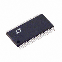
LTC1760CFW#PBF Linear Technology, LTC1760CFW#PBF Datasheet - Page 36

LTC1760CFW#PBF
Manufacturer Part Number
LTC1760CFW#PBF
Description
IC MANAGER BATTERY DUAL 48TSSOP
Manufacturer
Linear Technology
Datasheet
1.LTC1760CFWPBF.pdf
(44 pages)
Specifications of LTC1760CFW#PBF
Function
Charge Management
Battery Type
Smart Batteries
Voltage - Supply
6 V ~ 28 V
Operating Temperature
0°C ~ 70°C
Mounting Type
Surface Mount
Package / Case
48-TFSOP (0.240", 6.10mm Width)
Lead Free Status / RoHS Status
Lead free / RoHS Compliant
Available stocks
Company
Part Number
Manufacturer
Quantity
Price
LTC1760
APPLICATIO S I FOR ATIO
Sample calculation of I
Sample calculation of I
(R
SMBus Host communication:
36
Thermistor Impedance
THX
For thermistors that are IDEAL-RANGE:
I
(R1A +R
For thermistors that are HOT-RANGE:
I
(R1A +R
R
ground.
RXB = 54.9k
RXA = 1.13k
I
I
R
and I
R
R
GND.
R
GND.
I
SMBus Host and depends on the amount of bus
traffic.
I
with Battery1 or Battery2.
I
I
SAFETYX
SAFETYX
VLIM
ILIM
SMB
SMB_BATX
SMB_BATX
SMBALERT
THX
LIM_PU
LIM_PU
VLIMIT
ILIMIT
= 400), R
R
= V
LIMIT.
is the current used for communicating with the
is the impedance of the battery’s thermistor to
THX
= V
100k
3.3k
400
is the value of the resistance from I
is the value of the resistance from V
VCC2
THX
THX
= 4/64 • V
= 4/64 • V
(Ω)
is the typical pull-up impedance at V
= 34k.
VCC2
is the current used for communicating
= 350µA • 0.0155 = 5.425µA.
is defined in “Electrical Characteristics.”
)
)
VLIMIT
/(R
/(R
ILIMIT
VLIMIT
U
VCC2
= R
VCC2
DCIN_CHG
SAFETYX
Thermistor Range
+ R
UNDER_RANGE
ILIMIT
IDEAL_RANGE
OVER_RANGE
U
+ R
/(RXB + R
/(RXB + R
LIM_PU
LIM_PU
= 30k, V
with V
with two Li-Ion batteries
).
W
).
THX
THX
VCC2
CC2
) + 4/64 • V
) + 2/64 • V
= 5.2V
= 5.2V, and no
I
SAFETYX
LIMIT
U
1.05
42.2
218
LIMIT
LIMIT
(µA)
VCC2
to
VCC2
to
/
/
The total operating current through BAT1 and BAT2 when
AC is not present (I
where:
Sample calculation of I
Sample calculation with two Li-Ion batteries (R
400), V
Thermistor Impedance
I
I
I
= 1.3mA + 700µA + 218µA + 218µA +81µA + 81µA
+ 0µA + 5.4µA + 5.4µA + 0µA = 2.62mA
I
I
I
I
I
thermistor connected to SAFETY1 or SAFETY2.
I
R
ground.
RXB = 54.9k.
I
ing with Battery1 or Battery2 when AC in not present.
I
I
SMBus Host and depends on the amount of bus
traffic.
I
I
= 175µA + 80µA + 2.9µA + 2.9µA + 0µA + 2.4µA +
2.4µA + 0µA = 265µA
DCIN_CHG
VLIM
SMBALERT
BAT_NOAC
SMB
BAT
VCC2_AC0
SAFETYX
SAFETYX
SMB_BATX_ACO
SMB_BATX_AC0
SMB
BAT_NOAC
SMB
THX
R
is defined in “Electrical Characteristics.”
CC2
+ I
is the current used for communicating with the
+ I
+ I
is the impedance of the battery’s thermistor to
THX
400
SMB_BAT1_AC0
SMB_BAT1_AC0
ILIM
= 5.2V, and no SMBus Host communication:
is the current used to test the battery
= 2/64 • V
(Ω)
is defined in “Electrical Characteristics.”
= I
– I
= I
+ I
CH1
BAT
BAT
= 350µA • 0.00687 = 2.404µA.
is the current used for communicat-
SMB
BAT_NOAC
+ I
+ I
+ I
VCC2
VCC2_AC1
VCC2_AC0
VCC2_AC0
+ I
SAFETY
Thermistor Range
+ I
+ I
UNDER_RANGE
SMB_BAT1
/(RXB + R
SMB_BAT2_AC0
SMB_BAT2_AC0
) is given by:
with V
+ I
+ I
+ I
SAFETY1
SAFETY1
SAFETY1
+ I
THX
VCC2
SMB_BAT2
).
= 5.2V
+ I
+ I
+ I
+ I
+ I
I
SAFETYX
SMBALERT
SMBALERT
SAFETY2
SAFETY2
SAFETY2
2.9
THX
+
(µA)
=
+
+
+
1760f


