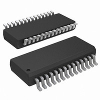
ISL6256AHAZ Intersil, ISL6256AHAZ Datasheet - Page 14

ISL6256AHAZ
Manufacturer Part Number
ISL6256AHAZ
Description
IC BATTERY CHARGER CTRLR 28-QSOP
Manufacturer
Intersil
Datasheet
1.ISL6256AHAZ.pdf
(26 pages)
Specifications of ISL6256AHAZ
Function
Charge Management
Battery Type
Lithium-Ion (Li-Ion), Lithium-Polymer (Li-Pol)
Voltage - Supply
7 V ~ 25 V
Operating Temperature
-10°C ~ 100°C
Mounting Type
Surface Mount
Package / Case
28-SSOP (0.150", 3.95mm Width)
Lead Free Status / RoHS Status
Lead free / RoHS Compliant
mode, where there is a timer to prevent the frequency from
dropping into the audible frequency range. It can achieve
duty cycle of up to 99.6%.
To prevent boosting of the system bus voltage, the battery
charger operates in standard-buck mode when CSOP-CSON
drops below 4.25mV. Once in standard-buck mode, hysteresis
does not allow synchronous operation of the DC/DC converter
until CSOP-CSON rises above 12.5mV.
An adaptive gate drive scheme is used to control the dead
time between two switches. The dead time control circuit
monitors the LGATE output and prevents the upper side
MOSFET from turning on until LGATE is fully off, preventing
cross-conduction and shoot-through. In order for the dead
time circuit to work properly, there must be a low resistance,
low inductance path from the LGATE driver to MOSFET
gate, and from the source of MOSFET to PGND. The
external Schottky diode is between the VDDP pin and BOOT
pin to keep the bootstrap capacitor charged.
Setting the Battery Regulation Voltage
The ISL6256 uses a high-accuracy trimmed band-gap
voltage reference to regulate the battery charging voltage.
The VADJ input adjusts the charger output voltage, and the
VADJ control voltage can vary from 0 to VREF, providing a
10% adjustment range (from 4.2V - 5% to 4.2V + 5%) on
CSON regulation voltage. An overall voltage accuracy of
better than 0.5% is achieved.
The per-cell battery termination voltage is a function of the
battery chemistry (consult the battery manufacturers to
determine this voltage)
• Float VADJ to set the battery voltage V
• Connect VADJ to VREF to set 4.41V × number of cells
• Connect VADJ to ground to set 3.99V × number of the
so, the maximum battery voltage of 17.6V can be achieved.
Note that other battery charge voltages can be set by
connecting a resistor divider from VREF to ground. The resistor
divider should be sized to draw no more than 100µA from
VREF; or connect a low impedance voltage source like the D/A
converter in the micro-controller. The programmed battery
voltage per cell can be determined by Equation 1:
An external resistor divider from VREF sets the voltage at
VADJ according to Equation 2:
V
V
CELL
VADJ
number of the cells
cells
=
=
0.175 V
VREF
⋅
×
VADJ
---------------------------------------------------------------------------------------------------------------- -
R
top_VADJ
+
3.99V
R
||
14
bot_VADJ
514kΩ
+
R
||
bot_VADJ
514kΩ
CSON
= 4.2V ×
||
514kΩ
ISL6256, ISL6256A
(EQ. 2)
(EQ. 1)
To minimize accuracy loss due to interaction with VADJ's
internal resistor divider, ensure the AC resistance looking
back into the external resistor divider is less than 25k.
Connect CELLS as shown in Table 1 to charge 2, 3 or 4 Li+
cells. When charging other cell chemistries, use CELLS to
select an output voltage range for the charger. The internal
error amplifier gm1 maintains voltage regulation. The voltage
error amplifier is compensated at VCOMP. The component
values shown in Figure 3 provide suitable performance for most
applications. Individual compensation of the voltage regulation
and current-regulation loops allows for optimal compensation.
Setting the Battery Charge Current Limit
The CHLIM input sets the maximum charging current. The
current set by the current sense-resistor connects between
CSOP and CSON. The full-scale differential voltage between
CSOP and CSON is 165mV for CHLIM = 3.3V, so the
maximum charging current is 4.125A for a 40mΩ sensing
resistor. Other battery charge current-sense threshold
values can be set by connecting a resistor divider from
VREF or 3.3V to ground, or by connecting a low impedance
voltage source like a D/A converter in the micro-controller.
Unlike VADJ and ACLIM, CHLIM does not have an internal
resistor divider network. The charge current limit threshold is
given by Equation 3:
To set the trickle charge current for the dumb charger, an
A/D output controlled by the micro-controller is connected to
CHLIM pin. The trickle charge current is determined by
Equation 4:
When the CHLIM voltage is below 88mV (typical), it will
disable the battery charge. When choosing the current
sensing resistor, note that the voltage drop across the
sensing resistor causes further power dissipation, reducing
efficiency. However, adjusting CHLIM voltage to reduce the
voltage across the current sense resistor R
accuracy due to the smaller signal to the input of the current
sense amplifier. There is a trade-off between accuracy and
power dissipation. A low pass filter is recommended to
eliminate switching noise. Connect the resistor to the CSOP
pin instead of the CSON pin, as the CSOP pin has lower
bias current and less influence on current-sense accuracy
and voltage regulation accuracy.
I
I
CHG
CHG
=
=
⎛
⎝
⎛
⎝
165mV
-------------------
TABLE 1. CELL NUMBER PROGRAMMING
165mV
-------------------
CELLS
R
R
GND
Float
VDD
1
1
⎞
⎠
⎞
⎠
⎛
⎝
⎛
⎝
V
--------------------- -
V
--------------------------------------- -
CHLIM
3.3V
CHLIM trickle
3.3V
⎞
⎠
,
⎞
⎠
CELL NUMBER
1
will degrade
4
3
2
September 14, 2010
FN6499.3
(EQ. 4)
(EQ. 3)


