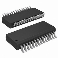
ISL6256AHAZ Intersil, ISL6256AHAZ Datasheet - Page 23

ISL6256AHAZ
Manufacturer Part Number
ISL6256AHAZ
Description
IC BATTERY CHARGER CTRLR 28-QSOP
Manufacturer
Intersil
Datasheet
1.ISL6256AHAZ.pdf
(26 pages)
Specifications of ISL6256AHAZ
Function
Charge Management
Battery Type
Lithium-Ion (Li-Ion), Lithium-Polymer (Li-Pol)
Voltage - Supply
7 V ~ 25 V
Operating Temperature
-10°C ~ 100°C
Mounting Type
Surface Mount
Package / Case
28-SSOP (0.150", 3.95mm Width)
Lead Free Status / RoHS Status
Lead free / RoHS Compliant
.
COMPENSATION BREAK FREQUENCY EQUATIONS
Choose R
from Equation 45.
Next, choose C
calculated from Equation 46.
f
f
f
f
f
f
R
C
ZERO1
ZERO2
LC
FILTER
POLE1
ESR
FIGURE 24. ASYMPTOTIC BODE PLOT OF THE VOLTAGE
VCOMP
VCOMP
=
-20
-40
-60
40
20
=
0
-------------------------------
(
CELLS
2π L C
0.1k
------------------------------------------- -
(
=
=
=
=
2π C
2
3
4
=
=
VCOMP
--------------------------------------------------- -
(
---------------------------------------------------------------------- -
(
⎛
⎜
⎝
------------------------------------------ -
(
2π R
2π C
------------------------------------------------------- -
2π R
1
2π R
⋅
(
-------------------------------------------------------------------------- -
(
⋅
0.7 F
0.3 F
CONTROL LOOP GAIN
⋅
⋅
o
⋅
⋅
1
o
VCOMP
⋅
⋅
⋅
R
)
SENSE
f
VCOMP
R
SENSE
F2
ZERO1
1
equal or lower than the value calculated
VCOMP
ESR
LC
LC
1
COMPENSATOR
MODULATOR
LOOP
⋅
1k
C
)
)
1
⋅
⋅
)
F2
(
(
⋅
equal or higher than the value
⋅
2π C
2π R
1
⋅
)
C
C
FREQUENCY (Hz)
R
TABLE 3.
o
OUT
1COMP
⋅
⋅
)
288kΩ
320kΩ
336kΩ
R
23
o
VCOMP
⎞
⎟
⎠
3
⋅
⋅
R
10k
f
ZERO2
⎛
⎜
⎝
SENSE
)
-------------------- -
R
4
R
)
+
4
f
LC
R
f
ESR
3
)
⎞
⎟
⎠
⋅
⎛
⎝
⋅
----------- -
gm1
100k
⎛
⎝
gm1
----------- -
f
5
POLE1
5
⎞
⎠
48kΩ
64kΩ
96kΩ
⎞
⎠
⋅
R
f
FILTER
⎛
⎜
⎝
4
R
-------------------- -
ISL6256, ISL6256A
(EQ. 39)
(EQ. 40)
(EQ. 41)
(EQ. 42)
(EQ. 43)
(EQ. 44)
3
(EQ. 46)
(EQ. 45)
R
+
4
1M
R
4
⎞
⎟
⎠
PCB Layout Considerations
Power and Signal Layers Placement on the PCB
As a general rule, power layers should be close together,
either on the top or bottom of the board, with signal layers on
the opposite side of the board. As an example, layer
arrangement on a 4-layer board is shown below:
Separate the power voltage and current flowing path from
the control and logic level signal path. The controller IC will
stay on the signal layer, which is isolated by the signal
ground to the power signal traces.
Component Placement
The power MOSFET should be close to the IC so that the
gate drive signal, the LGATE, UGATE, PHASE, and BOOT,
traces can be short.
Place the components in such a way that the area under the
IC has less noise traces with high dv/dt and di/dt, such as
gate signals and phase node signals.
Signal Ground and Power Ground Connection
At minimum, a reasonably large area of copper, which will
shield other noise couplings through the IC, should be used
as signal ground beneath the IC. The best tie-point between
the signal ground and the power ground is at the negative
side of the output capacitor on each side, where there is little
noise; a noisy trace beneath the IC is not recommended.
GND and VDD Pin
At least one high quality ceramic decoupling cap should be
used to cross these two pins. The decoupling cap can be put
close to the IC.
LGATE Pin
This is the gate drive signal for the bottom MOSFET of the
buck converter. The signal going through this trace has both
high dv/dt and high di/dt, and the peak charging and
discharging current is very high. These two traces should be
short, wide, and away from other traces. There should be no
other traces in parallel with these traces on any layer.
PGND Pin
PGND pin should be laid out to the negative side of the
relevant output cap with separate traces.The negative side
of the output capacitor must be close to the source node of
the bottom MOSFET. This trace is the return path of LGATE.
PHASE Pin
This trace should be short, and positioned away from other
weak signal traces. This node has a very high dv/dt with a
1. Top Layer: signal lines, or half board for signal lines and
2. Signal Ground
3. Power Layers: Power Ground
4. Bottom Layer: Power MOSFET, Inductors and other
the other half board for power lines
Power traces
September 14, 2010
FN6499.3


