STLVDS385BTR STMicroelectronics, STLVDS385BTR Datasheet - Page 7
STLVDS385BTR
Manufacturer Part Number
STLVDS385BTR
Description
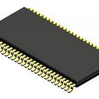
IC FLAT PANEL DISPLY DVR 56TSSOP
Manufacturer
STMicroelectronics
Type
LVDSr
Datasheet
1.STLVDS385BTR.pdf
(19 pages)
Specifications of STLVDS385BTR
Display Type
FPD
Voltage - Supply
3 V ~ 3.6 V
Operating Temperature
0°C ~ 70°C
Mounting Type
Surface Mount
Package / Case
56-TSSOP
Number Of Drivers
4
Number Of Receivers
28
Data Rate
595 Mbps
Operating Supply Voltage
3.3 V
Maximum Power Dissipation
130 mW
Maximum Operating Temperature
+ 70 C
Minimum Operating Temperature
- 10 C
Mounting Style
SMD/SMT
Supply Voltage (max)
3.6 V
Supply Voltage (min)
3 V
Lead Free Status / RoHS Status
Contains lead / RoHS non-compliant
Current - Supply
-
Interface
-
Configuration
-
Digits Or Characters
-
Lead Free Status / Rohs Status
Details
Other names
497-2150-2
Available stocks
Company
Part Number
Manufacturer
Quantity
Price

Part Number:
STLVDS385BTR
Manufacturer:
ST
Quantity:
20 000


Table 10.
Symbol
t
t
t
t
t
t
t
t
t
t
t
t
t
t
t
t
t
t
t
t
t
t
t
t
t
t
t
t
LLHT
TPP0
TPP1
TPP2
TPP3
TPP4
TPP5
TPP6
TPP0
TPP1
TPP2
TPP3
TPP4
TPP5
TPP6
TPP0
TPP1
TPP2
TPP3
TPP4
TPP5
TPP6
LLLT
CCD
CCD
STC
HTC
JCC
LVDS low-to-high transition time
(Figure
LVDS high-to-low transition time
(Figure
Transmitter output pulse position for bit 0
(Figure 12
Transmitter output pulse position for bit 1
Transmitter output pulse position for bit 2
Transmitter output pulse position for bit 3
Transmitter output pulse position for bit 4
Transmitter output pulse position for bit 5
Transmitter output pulse position for bit 6
TxIN setup to TxCLK IN
TxIN hold to TxCLK IN
TxCLK IN to TxCLK OUT delay
TxCLK IN to TxCLK OUT delay
Transmitter jitter cycle-to-cycle
-
Transmitter switching characteristics (V
noted. Typical values are referred to T
Note
4)
5)
5)
-
-
-
Note
Note
Note
Parameter
3)
3)
3)
(Figure
(Figure
(Figure 12
7)
(Figure
(Figure
7)
8) T
8)
A
f = 40 MHz
f = 65 MHz
f = 85 MHz
f = 85 MHz
f = 65 MHz
f = 40 MHz
A
= 25 °C)
= 25°C, V
Test conditions
CC
= 3.3 V, T
CC
= 3.3V
J
= -10 to 70 °C unless otherwise
10.46
14.04
17.61
21.18
10.79
12.99
-0.25
-0.20
-0.20
Min.
3.32
6.89
2.00
4.20
6.39
8.59
1.48
3.16
4.84
6.52
8.20
9.88
2.5
3.8
2.8
0
10.71
14.29
17.86
21.43
10.99
13.19
10.08
Typ.
0.75
0.75
3.57
7.14
2.20
4.40
6.59
8.79
1.68
3.36
5.04
6.72
8.40
110
210
350
0
0
0
10.96
14.54
18.11
21.68
11.19
13.99
10.28
Max.
0.25
3.82
7.39
0.20
2.40
4.60
6.79
8.99
0.20
1.88
3.56
5.24
6.92
8.60
150
230
370
1.5
1.5
6.3
7.1
Unit
ns
ns
ns
ns
ns
ns
ns
ns
ns
ns
ns
ns
ns
ns
ns
ns
ns
ns
ns
ns
ns
ns
ns
ns
ns
ns
ns
ps
7/19
Related parts for STLVDS385BTR
Image
Part Number
Description
Manufacturer
Datasheet
Request
R

Part Number:
Description:
STMicroelectronics [RIPPLE-CARRY BINARY COUNTER/DIVIDERS]
Manufacturer:
STMicroelectronics
Datasheet:
Part Number:
Description:
STMicroelectronics [LIQUID-CRYSTAL DISPLAY DRIVERS]
Manufacturer:
STMicroelectronics
Datasheet:

Part Number:
Description:
BOARD EVAL FOR MEMS SENSORS
Manufacturer:
STMicroelectronics
Datasheet:
Part Number:
Description:
NPN TRANSISTOR POWER MODULE
Manufacturer:
STMicroelectronics
Datasheet:
Part Number:
Description:
TURBOSWITCH ULTRA-FAST HIGH VOLTAGE DIODE
Manufacturer:
STMicroelectronics
Datasheet:
Part Number:
Description:
Manufacturer:
STMicroelectronics
Datasheet:
Part Number:
Description:
DIODE / SCR MODULE
Manufacturer:
STMicroelectronics
Datasheet:
Part Number:
Description:
DIODE / SCR MODULE
Manufacturer:
STMicroelectronics
Datasheet:
Part Number:
Description:
Search -----> STE16N100
Manufacturer:
STMicroelectronics
Datasheet:
Part Number:
Description:
Search ---> STE53NA50
Manufacturer:
STMicroelectronics
Datasheet:
Part Number:
Description:
NPN Transistor Power Module
Manufacturer:
STMicroelectronics
Datasheet:
Part Number:
Description:
DIODE / SCR MODULE
Manufacturer:
STMicroelectronics
Datasheet: