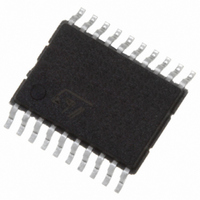
STPM11ATR STMicroelectronics, STPM11ATR Datasheet - Page 37

STPM11ATR
Manufacturer Part Number
STPM11ATR
Description
IC ENERGY METER 1 PHASE 20TSSOP
Manufacturer
STMicroelectronics
Datasheet
1.STPM13ATR.pdf
(46 pages)
Specifications of STPM11ATR
Input Impedance
100 KOhm
Measurement Error
0.1%
Voltage - I/o High
1.5V
Voltage - I/o Low
0.8V
Current - Supply
4.7mA
Voltage - Supply
3 V ~ 5.5 V
Operating Temperature
-40°C ~ 85°C
Mounting Type
Surface Mount
Package / Case
20-TSSOP
Meter Type
Single Phase
Output Voltage
+/- 0.4 V
Output Current
150 mA
Input Voltage
3 V to 5.5 V
Operating Temperature Range
- 40 C to + 85 C
Mounting Style
SMD/SMT
Lead Free Status / RoHS Status
Lead free / RoHS Compliant
Other names
497-5984-2
STPM11, STPM12, STPM13, STPM14
9
Table 17.
Table 18.
Symbol
Symbol
Cv, Ci
Av, Ai
Vbg
Gp
Vn
DL
fM
In
Si
P
Line RMS current
Line RMS voltage
Power sensitivity
Shunt Sensor
Reference voltage
Clock
Amplification of ADC
Gain of voltage and current decimation filters
Calibration data range
AW Bit position that generates LED signal
STPM1x calibration
Energy meters based on STPM1x devices are calibrated on the frequency of the output
pulse signal.
The devices are comprised of two independent meter channels for line voltage and current
respectively. Each channel includes its own digital calibrator, to adjust the voltage and
current signals coming from the sensors in the range of ±12.5% in 256 steps. A digital filter
is included to remove any signal DC component.
The devices produce an energy output pulse signal whose frequency is proportional to the
measured active energy.
The devices have an embedded memory, 54 bits, used for configuration and calibration
purposes. The value of these bits can be written temporarily or permanently through CFGI
communication channel.
The basic information needed to start the calibration procedure is found in
Table
Calibration entries
The following typical STPM01 parameters and constants are also known:
Device calculation constants
Av is constant. While, Ai is chosen according to the sensor
Gv and Gi are constant
Cv and Ci are 8bits register (CHV, CHP and CHS)
From the values above and for both the given amplification factor and initial calibration data,
the following target values can be calculated:
Considering that Ci=0 generates a correction of 75% and that Ci=128 determines a
correction factor of 87.5%, and the same for Cv, the total correction for the power stands
Description
18:
Description
(230 V)
(5 A)
(LED: P=128000 pulses/kWh, Stepper Motor: PM=P/64= 2000 pulses/kWh)
0,42 mV/A
Doc ID 13167 Rev 7
Value
(1.23 V ± 2%)
(2
[4 ± 1%, (8, 16, 24, 32) ± 2%)]
(0.504008)
(min = 0, ini = 128, max = 255)
(2
23
11
)
Hz ± 50ppm)
Value
STPM1x calibration
Table 17
and
37/46


