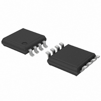
PCA9530DP,118 NXP Semiconductors, PCA9530DP,118 Datasheet - Page 22

PCA9530DP,118
Manufacturer Part Number
PCA9530DP,118
Description
IC LED DRIVER RGB 8-TSSOP
Manufacturer
NXP Semiconductors
Type
RGB LED Driverr
Datasheet
1.PCA9530D118.pdf
(24 pages)
Specifications of PCA9530DP,118
Package / Case
8-TSSOP
Topology
Open Drain, PWM
Number Of Outputs
2
Internal Driver
Yes
Type - Primary
Backlight, LED Blinker
Type - Secondary
RGB
Frequency
400kHz
Voltage - Supply
2.3 V ~ 5.5 V
Mounting Type
Surface Mount
Operating Temperature
-40°C ~ 85°C
Current - Output / Channel
25mA
Internal Switch(s)
Yes
Low Level Output Current
6.5 mA
Operating Supply Voltage
2.3 V to 5.5 V
Maximum Supply Current
500 uA
Maximum Power Dissipation
400 mW
Maximum Operating Temperature
+ 85 C
Mounting Style
SMD/SMT
Minimum Operating Temperature
- 40 C
Lead Free Status / RoHS Status
Lead free / RoHS Compliant
Voltage - Output
-
Efficiency
-
Lead Free Status / Rohs Status
Details
Other names
568-1831-2
935276297118
PCA9530DP-T
935276297118
PCA9530DP-T
Available stocks
Company
Part Number
Manufacturer
Quantity
Price
Company:
Part Number:
PCA9530DP,118
Manufacturer:
XILINX
Quantity:
1 193
NXP Semiconductors
17. Revision history
Table 17.
PCA9530_3
Product data sheet
Document ID
PCA9530_3
Modifications:
PCA9530_2
(9397 750 14093)
PCA9530_1
(9397 750 13631)
Revision history
Release date
20090226
20041001
20040914
•
•
•
•
•
•
•
•
•
•
The format of this data sheet has been redesigned to comply with the new identity guidelines of
NXP Semiconductors.
Legal texts have been adapted to the new company name where appropriate.
Section 6.6 “External
Figure 10 “Write to
Figure 11 “Read from
– symbol changed from “t
– symbol changed from “t
Table 11 “Limiting
– parameter description for V
– symbol/parameter changed from “I
Table 12 “Static
– title of this table changed from “DC characteristics” to “Static characteristics”
– descriptive line below table title: deleted “TYP at 3.3 V and 25 C” (this is moved to new
– I
– parameter description for symbol I
– added (new)
Table 13 “Dynamic
– changed parameter description for f
– (old) symbols “t
– symbol/parameter changed from “t
– symbol/parameter changed from “t
– symbol/parameter changed from “t
– symbol/parameter changed from “t
– symbol/parameter changed from “t
added soldering information
added
input/output pin”
current on pin LEDn”
Table note
“additional quiescent standby current”
conditions for LOW-level and HIGH-level
time”
stb
Max value changed from “3.0 A” to “5.0 A”
Table 16 “Abbreviations”
[1], with its reference at column heading “Typ”
Data sheet status
Product data sheet
Product data sheet
Product data sheet
characteristics”:
Table note
values”:
VD;DAT
characteristics”:
register”: symbol changed from “t
Rev. 03 — 26 February 2009
RESET”, 1
register”:
(L)” and “t
ph
ps
[2], and its reference at I
” to “t
” to “t
I/O
st
changed from “DC voltage on an I/O” to “voltage on an
su(D)
h(D)
sentence: changed from “t
VD;DAT
”
I/O
PV
PS
W
REC
RESET
”
DD
SCL
, Reset pulse width” to “t
, DC output current on an I/O” to “I
, output data valid” to “t
, input data setup time” to “t
, Reset recovery time” to “t
changed from “additional standby current” to
(H)” merged to “t
from “operating frequency” to “SCL clock frequency”
, Time to reset” to “t
Change notice
-
-
-
pv
DD
” to “t
VD;DAT
v(Q)
W
” to “t
”
v(Q)
rst
w(rst)
” and added separate
2-bit I
, reset time”
, data output valid time”
Supersedes
PCA9530_2
PCA9530_1
-
w(rst)
su(D)
rec(rst)
, reset pulse width”
, data input set-up
2
”
C-bus LED dimmer
, reset recovery time”
PCA9530
O(LEDn)
© NXP B.V. 2009. All rights reserved.
, output
22 of 24


