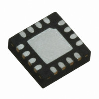
STLD20CP1PQR STMicroelectronics, STLD20CP1PQR Datasheet

STLD20CP1PQR
Specifications of STLD20CP1PQR
STLD20CP1PQR
Available stocks
Related parts for STLD20CP1PQR
STLD20CP1PQR Summary of contents
Page 1
... The current feedback control of the step-up provides excellent line transient response, making it particularly Table 1. Device summary Order code STLD20CP1PQR November 2007 QFN16 (3x3 mm) suitable for battery-powered applications possible to select the value of the current flowing through the power white LED using two external resistors to choose the current value in torch mode or flash mode ...
Page 2
Contents 1 Diagram . . . . . . . . . . . . . . . . . . . . . . . . . . . . . . . . . . . . . ...
Page 3
Diagram Figure 1. Block diagram 3/19 ...
Page 4
Pin description Figure 2. Pin configuration (top view) Table 2. Pin description Symbol Pin n° SGND 1 DM1 2 DM2 3 FB_SU 4 OUT_SU PGND FB_CP 11 OUT_CP 12 ...
Page 5
Maximum ratings Table 3. Absolute maximum ratings Symbol IN DC supply SW Switch node OUT_SU Output step-up FB_SU Feedback step-up OUT_CP Output charge pump FB_CP Feedback of charge pump PGND Power ground IT Torch current selection IF Flash current ...
Page 6
Truth tables Table 5. Truth table selection mode step-up DM1 Table 6. Truth table selection mode charge pump SEL Figure 3. Typical application circuit 6/19 DM2 0 Shutdown step- ...
Page 7
Electrical characteristics Table 7. Electrical characteristics for STLD20CP1 ( 2.2 µF, V O1,2 O_SU DM2 = 1.6 V, typ. values @ 25 °C, unless otherwise specified) Symbol Parameter Supply section V Operating input voltage I Under-voltage lockout ...
Page 8
Table 7. Electrical characteristics for STLD20CP1 (continued 2.2 µ 2.2 µF, V O1,2 µH, DM1 = DM2 = 1.6 V, typ. values @ 25 °C, unless otherwise specified) Symbol Parameter V-DM1 V- L DM2 V- L ...
Page 9
Application information 6.1 Step-up The STLD20CP1 is a PWM controller working at a 1.3 MHz frequency, designed to function in discontinuous mode. The LED current regulation for the backlighting is achieved by connecting the FB_SU terminal at the top ...
Page 10
Figure 5. PWM dimming method from 0% to 60% Likewise, by forcing DM1 low and applying a PWM signal on pin DM2 possible to achieve dimming from DM2, the device performs dimming from 60% to ...
Page 11
The eleventh pulse sets the LED current back to I shows a timing diagram for single-wire pulse dimming. Analog dimming can be achieved by connecting a resistor network to the FB pin 6.3 Peak inductor current limitation ...
Page 12
Thermal shutdown The device includes a thermal limit circuit that shuts down the IC at approximately +180 °C, and return to operation after the IC cools by approximately 20 °C. Figure 8. Single-wire pulse dimming Figure 9. Analog continuous ...
Page 13
Figure 10. Single camera shot Figure 11. Multiple shots (graph is not to scale) 13/19 ...
Page 14
Package mechanical data In order to meet environmental requirements, ST offers these devices in ECOPACK® packages. These packages have a lead-free second level interconnect. The category of second level interconnect is marked on the package and on the inner ...
Page 15
QFN16 (3x3 mm) mechanical data mm. Dim. Min. Typ. A 0.80 0.90 A1 0.02 A3 0.20 b 0.18 0.25 D 3.00 D2 1.55 1.70 E 3.00 E2 1.55 1.70 e 0.50 K 0.20 L 0.30 0. ...
Page 16
Tape & reel QFNxx/DFNxx (3x3) mechanical data Dim. Min 12 16/19 mm. Typ. Max. Min. 180 13.2 0.504 0.795 2.362 14.4 3.3 3.3 1 inch. Typ. ...
Page 17
Figure 12. QFN16 (3x3 mm) footprint recommended data 17/19 ...
Page 18
Revision history Table 8. Document revision history Date Revision 14-Nov-2007 1 20-Nov-2007 2 18/19 Changes Initial release. Modified: Table 1. ...
Page 19
... Information in this document is provided solely in connection with ST products. STMicroelectronics NV and its subsidiaries (“ST”) reserve the right to make changes, corrections, modifications or improvements, to this document, and the products and services described herein at any time, without notice. All ST products are sold pursuant to ST’s terms and conditions of sale. ...


